


18 Section 5: Maintenance
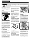
wheels roll freely when the Wheel Gear
Lever is in ENGAGE, the wheel gear cable
needs to be adjusted as described below.
1. With engine shut off and spark plug
wire disconnected, put Wheel Gear Lever
in ENGAGE.
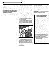
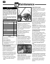
2. Loosen top adjustment nut (A, Figure
5-4) on wheel gear cable bracket located
on left side rear of transmission.
3. Push wheel gear cable (B) down and
roll tiller slightly forward or backward until
eccentric lever (C) engages (locks)
wheels. Hold cable in that position and
tighten top (A) and bottom (D) adjustment
nuts.
4. Move Wheel Gear Lever into ENGAGE
and DISENGAGE several times to check
adjustment. The wheels should not roll
when lever is in ENGAGE, but should roll
when lever is in DISENGAGE. Readjust
cable as required.
OFF SEASON STORAGE
To prepare tiller for extended storage:
1. Clean tiller and engine.
2. Do routine tiller lubrication (see Tiller
Lubrication) and check for loose parts and
hardware (see Check Hardware).
3. Protect engine by performing the rec-
ommended engine storage instructions in
Engine Owner’s Manual. NOTE: Be sure to
protect fuel lines, carburetor and fuel tank
from gum deposits by removing fuel or by
treating fuel with fuel stabilizer (follow
engine manufacturer’s recommendations).
4. Store unit in a clean, dry area.
5. Never store tiller with fuel in fuel tank in
an enclosed area where gas fumes could
reach an open flame or spark, or where
ignition sources are present (space
heaters, hot water heaters, furnaces, etc.).
BOLO TINES
Tines will wear with use and should be
inspected at the beginning of each tilling
season and after every 30 operating hours.
Tines can be replaced individually or as a
complete set. Never inspect or service
tines unless engine is stopped, spark plug
wire is disconnected, and ignition key is
removed on electric start models.
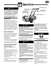
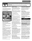
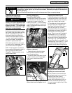
A. Tine Inspection:
With use, tines will become shorter, nar-
rower and pointed (Figure 5-5). Badly
worn tines result in loss of tilling depth
and reduced effectiveness when chopping
up and turning under organic matter. Use
Figure 5-5 as a guide to when to replace
tines.
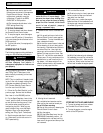
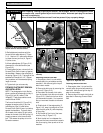
B. Removing a Single Tine:
1. With engine shut off and spark plug
wire disconnected, remove two screws
and nuts that attach a single tine to a tine
holder (Figure 5-6). If needed, use pene-
trating oil to help free nuts.
2. When installing a single tine, be sure to
position it so that its cutting edge enters
the soil first as the tiller moves forward.
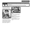
C. Removing and Installing
Tine Assemblies:
1. With engine shut off and spark plug
wire disconnected, remove tine hood by
removing two attaching screws at rear of
hood and two attaching screws at front of
hood.
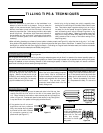
2. If removing both tine assemblies, mark
them “left” and “right” before removal.
Remove the screw and locknut that secure
the tine assembly to the tine shaft (Photo
5-7). If necessary, use a rubber mallet to
tap tine assembly outward off shaft.
3. Before reinstalling a tine assembly,
inspect tine shaft for rust, rough spots or
burrs and file or sand as needed. Apply a
thin coat of grease to shaft.
4. Install each tine assembly so that the
cutting edge of tines enter soil first when
tiller moves forward. Secure tine assem-
bly to tine shaft using screw and locknut
previously removed. Tighten securely.
5. Replace tine hood using four screws
previously removed. Tighten securely.
Before inspecting, cleaning or servicing the machine, shut off engine, wait for all moving parts to come to
a complete stop, remove ignition key on electric start models, disconnect spark plug wire and move wire
away from spark plug.
Failure to follow these instructions can result in serious personal injury or property damage.
WARNING
Figure 5-4: Wheel gear cable assembly.
B
A
C
D
Figure 5-5: Checking tines for wear.
New Tine
Moderate Wear
Figure 5-6: Removing single tine.
Cutting Edge
of Tine
Figure 5-7: Removing tine assembly.
Cutting Edge of Tine
Replace