


8 Section 2: Assembly
3. If oil does not flow from the check
hole, add oil as follows:
NOTE: Do not use automatic transmission
fluid or motor oil in the transmission.
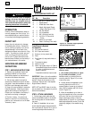
(a) Clean area around the fill hole (N,
Figure 2-10) and unscrew gear oil fill
plug.
(b) If adding only a few ounces of gear oil,
use API rated GL-4 or GL-5 gear oil
having a viscosity of SAE 140, SAE
85W-140 or SAE 80W-90. If refilling
an empty transmission, use only GL-4
gear oil having a viscosity of SAE
85W-140 or SAE 140.
(c) Using a clean funnel, slowly add gear
oil until it flows from the gear oil level
check hole (N, Figure 2-10).
(d) Reinstall and tighten securely the gear
oil fill plug (M, Figure 2-9).
STEP 5: ADD MOTOR OIL TO ENGINE
The tiller is shipped without oil in the
engine.
IMPORTANT: Do not start the engine
without first adding motor oil. Severe
engine damage will result if the engine is
run without oil.
1. Refer to the separate Engine Owner’s
Manual for motor oil specifications and
capacities.
2. With the unit on level ground, move
the Depth Regulator Lever (L, Figure 2-8)
up or down until the engine is level.
3. Add motor oil as described in the
Engine Owner’s Manual.
4. Move the Depth Regulator Lever all the
way down until the highest notch is
engaged. This places the tines in the
“travel” position.
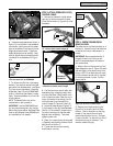
STEP 6: ATTACH WHEEL GEAR LEVER
1. Insert the Wheel Gear Lever (P, Figure
2-11) up through the slot in the control
panel that is labeled “WHEEL GEAR.”
2. Insert two #10-32 x 1/2" round head
screws down through the “+” marks on
the control panel decal and securely attach
the wheel gear mounting bracket using
two #10 lockwashers and #10-32 nuts.
3. Using a board, tap the Wheel Gear
Lever knob securely onto the lever.
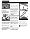
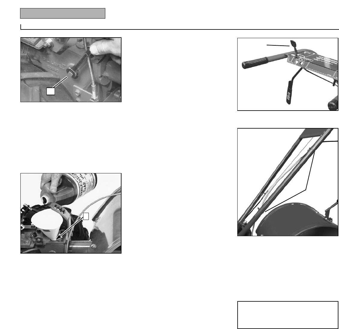
4. Secure the wheel gear cable to the left-
side handlebar with two plastic ties
(S, Figure 2-12), located about two feet
apart. Snip off any excess tie length with
scissors.
STEP 7: CHECK AIR PRESSURE
IN TIRES
Use a tire pressure gauge to check the air
pressure in both tires. Deflate or inflate
both tires equally to 15-to-20 PSI (pounds
per square inch). Be sure that both tires
are inflated equally or the unit will pull to
one side.
STEP 8: CHECK HARDWARE FOR
TIGHTNESS
Inspect the hardware on the unit and
tighten any loose screws, bolts and nuts.
This completes the assembly steps.
Be sure to read the rest of this Manual
before you operate your tiller.
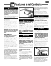
Figure 2-9: Gear oil level check plug.
M
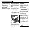
Figure 2-10: Adding gear oil.
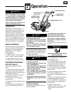
Figure 2-11: Attach Wheel Gear Lever.
P
N
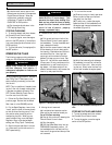
Figure 2-12: Attach wheel gear cable with
cable ties (S).
S