


Section 2: Assembly 7
6. Thread the height adjustment screw (F,
Figure 2-2) into the hole in the handlebar
cross-brace, making sure that the raised
keys on the washer fit into the slot on the
height adjustment bracket. Tighten the
height adjustment screw securely. Next,
securely tighten the two screws and nuts
in the ends of the handlebar (M, Figure
2-2).
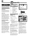
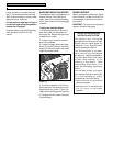
7. To remove the tiller from its shipping
platform, first carefully unwrap the wheel
gear cable (with attached lever - see Figure
2-4) from around the chassis. Move the
Wheel Gear Lever (G) to the DISENGAGE
position--this allows the wheels to rotate
freely. Use the handlebars to roll the tiller
off the platform.
NOTE: The Wheel Gear Lever will be
installed later in this procedure.
IMPORTANT: Use the DISENGAGE posi-
tion only when the engine is not running.
Before starting the engine, the Wheel Gear
Lever must be placed in the ENGAGE posi-
tion (see Section 3 for details).
STEP 3: ATTACH FORWARD CLUTCH
CONTROL CABLE
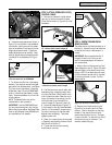
1. Remove any fasteners (rubber bands,
tape, etc.) that may secure the Forward
Clutch Control levers (J, Figure 2-5) to the
handlebar.
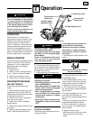
2. The forward clutch control cable (with
attached spring) is hanging loosely near
the right side wheel. Being careful not to
kink or stretch the cable, insert the z-con-
nector (at the end of the spring) into the
hole at the end of the forward clutch
control linkage (K, Figures 2-5 and 2-6).
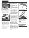
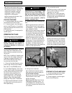
3. Attach the cable adjuster (Figure 2-7)
to the bracket on the right-side handlebar.
Use two 1/2" wrenches to loosen the two
jam nuts just enough to slide the cable
adjuster onto the bracket. Then hand
tighten the jam nuts.
4. Check for correct tension as instructed
in Checking and Adjusting Forward Clutch
Belt Tension in Section 5.
5. Tighten the two jam nuts securely
when tension is correct.
STEP 4: CHECK TRANSMISSION
GEAR OIL LEVEL
The transmission was filled with gear oil at
the factory. However, be sure to check the
oil level at this time to make certain it is
correct.
IMPORTANT: Do not operate the tiller if
the gear oil level is low. Doing so will
result in severe damage to the transmis-
sion components.
1. With the tiller on level ground, pull the
Depth Regulator Lever (L, Figure 2-8) back
and then slide it to the second notch from
the top. NOTE: If the lever does not move,
lift the tine hood flap and look for a plastic
tie securing the lever in place. Cut and
remove the tie.
2. Remove the oil level check plug (M,
Figure 2-9) on the left-side of the trans-
mission. (Due to dried paint on the plug
threads, it may require some force to
remove the plug the first time.) The gear
oil level is correct if oil starts to flow out of
the hole as the plug is removed. If so,
securely reinstall the plug.
Figure 2-3 Attach handlebars.
Figure 2-4: Carefully unwrap Wheel Gear
Lever and move lever to DISENGAGE.
C
N
P
O
➥
Figure 2-5: Forward Clutch Control levers
(J). Forward clutch control linkage (K).
K
J
G
Figure 2-6: Forward clutch control spring
connection to forward control linkage.
K
Completed
Connection
Figure 2-7
Jam
Nuts
Cable
Adjuster
Figure 2-8: Put lever in second notch.
L