ASSEMBLY
SE6 05/05 Assembly Section 3-6
© 2005 Alamo Group Inc.
ASSEMBLY
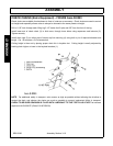
TAILWHEEL- ASSEMBLY PULL-TYPE MOWER (FIGURE Asm-R-0078)
To assemble the Mower’s Tail Wheels, follow the procedures listed below. Note: Certain assembly steps may
have been performed by the manufacturer before delivery.
1. Securely block the mower 12-18” off the ground.
2. To attach the wheel and tire assemblies (1) to the axle weldment (8), center a bushing (2) on each side of
the tail wheels. Place tail wheel and bushings inside fork of axle weldment and align holes of wheel,
bushing, and fork. Insert spindle weldment (3) through fork, bushings, and wheel and secure in position
with a 1” locknut (4).
3. Place axle lug (5) between the large set of axle weldment beam lugs (lugs will have two holes). Axle lug
should be positioned with its curvature facing the direction of the tailweels. Retain the axle lug to the axle
weldment with two 1”x 2-1/2” bolts (6) and 1” locknuts (7).
4. Position axle weldment beam farthest lugs to the outside of the two farthest lugs on the mower deck. The
axle beam must be positioned with the axle lug to (5) to the top. Insert bushing ( 21) into lugs of axle and
3/4” washer (10) against bushing. Align holes of lugs and bushings and retain axle to mower deck with two
3/4” x 1-3/4” bolts (9) and 3/4” locknuts (11).
5. Place axle cylinder lugs (16) to the outside of welded lugs behind gearbox. Align holes and retain all four
pieces in position with two 5/8” x 3-1/2” bolts (17) and 5/8” locknuts (18).
6. Place bushing (20) into end hole of leveling rod (19). Position leveling rod end hole and bushing between
remaining set of lugs on axle weldment, align holes, and retain in position with a 3/4” x 1-3/4” bolt (9) and
3/4” locknut (11). Note: The opposite end of the adjustment rod is attached during Tongue Assembly.
7. Align one rachet (12) end fork to the outside of the axle lug (5) top hole and retain in place using the short
pivot pin (13) and cotter pin (14).
8. Align other rachet end fork between set up upright bolted lugs on mower deck behind gearbox. Insert long
pivot pin (15) through lugs and rachet end fork and retain in position with pins. Note: The rachet is used to
raise and lower the mower deck. A hydraulic cylinder can be installed in its position to allow for
manipulation of deck height while driving.
9. Tighten all bolts and nuts per recommended torque at this time.


