


MAINTENANCE
SE6 05/05 Maintenance Section 5-12
© 2005 Alamo Group Inc.
MAINTENANCE
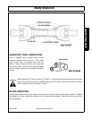
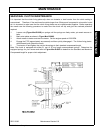
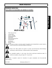
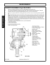
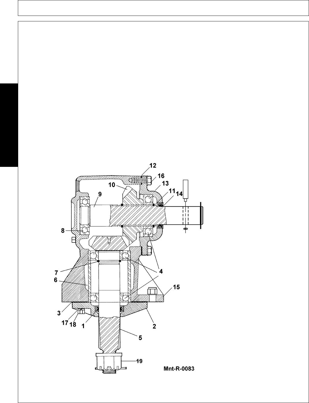
GEARBOX DISASSEMBLY (Figure Mnt-R-0083)
1. Remove 6 capscrews (Ref.#16) from input shaft bearing housing (Ref. #13).
2. Tap around circumference of bearing housing (Ref. #13) to loosen housing and shims. Then pull
complete shaft (Ref. #9) and housing assembly (See Fig. 10) out of main housing.
3. Remove 4 capscrews (Ref #18), break gasket loose, and then remove the bearing retainer cap (Ref
#2).
4. Output shaft assembly must be removed from main housing by driving or pulling shaft out bottom end.
NOTE: Once lower bearing is out of housing the complete assembly will drop down until top bearing
engages lower bearing bore. To complete removal of output shaft assembly it is necessary to keep
shaft aligned on center line of housing when removing top bearing out bottom end. Normally the
simplest method of removing the output shaft assembly is to attach a slide hammer puller to the shaft
and use that to pull the shaft out.
5. The gearbox is now disassembled into four (4) sub-assemblies:
1.Input shaft assembly
2.Output shaft assembly
3.Lower bearing retainer assembly
4.Main housing assembly
1.Seal Output Shaft
2.Cap, Bearing Retainer, (Output)
3.Gasket, Output, Cap
4.Bearing, Ball
5.Shaft, (Output Pinion)
6.Spacer, Bearing, (Output)
7.Snap Ring
8.Bearing, (Input Rear)
9.Shaft, (Input)
10.Gear (Input)
11.Retaining Ring
12.Shim, Side Housing
13.Housing, Side or Input
14.Seal, Input
15.Housing, Main
16.Bolt, (3/8" x 1")
17.Lockwasher (3/8")
18.Bolt, (3/8" x 1-1/4")
19.Slotted Nut