


The Raypak Low Nox Pool Heaters are certified and
tested under the ANSI Z21.56.CSA 4.7 Standards for gas
fired pool heaters.
The heater should be installed to meet all local codes, the
latest editions of the National Fuel Gas Code Z223.1 and
the National Electrical Code, ANSI/NFPA 70.
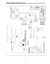
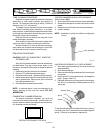
OPERATION
On call for heat, the ignition system, consisting of an
electronic spark module, gas pilot system is energized.
Providing pilot is proven blower will start running, the
main gas valve will open and the heater will operate.
When the operating control is satisfied the heater will
shut down.
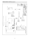
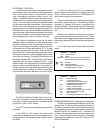
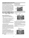
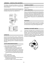
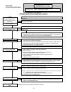
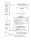
START-UP PROCEDURES (S8610B)
1.Turn on power to the heater with gas supply off.
2.Check ignition module as follows:
a. Set the thermostat or controller to call for heat.
b. Watch for continuous spark at the pilot burner.
c. Check the ignition spark operation. Time must be
within the lockout timing period (15 or 90 seconds).
d. Turn control down to end call for heat and wait 60
seconds on lockout models before beginning step
3.
3.Turn on gas supply.
4.Set controller to call for heat.
5.System should start as follows:
a. Spark will turn on and pilot gas valve will open and
the blower will begin running.
b. Heater will operate until call for heat is satisfied.
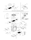
ADDENDA: LOW NOx POOL HEATERS
Fig # 9361
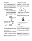
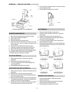
FLAME ROLL-OUT SAFETY SWITCH
The heater is equipped with a cutoff device to prevent
flame roll-out in the event the heat exchanger becomes
blocked. This is a "manual reset" type roll-out switch that
must be reset by a service technician after any over
temperature conditions have been fixed. Excessive
restriction in the heat exchanger flue passage may cause
the switch to disable the heater.
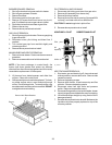
BURNER ADJUSTMENT
This burner assembly does not require any primary air
adjustments.
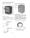
VISUAL INSPECTION
Flame can be observed through the slot opening above
the plenum. Flame color is blue and evenly spread on the
top surface of the burner. At least every three months a
visual inspection should be made of the burners. In case
flame lifting is observed on the burner, check gas pres-
sure on manifold. Gas pressure in manifold should be
3.9" W.C.
ELECTRICAL
Be sure that electrical service to the boiler has proper
overload fuse or circuit breaker protection, wire size and
connections which comply with all applicable codes.
30