


21
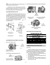
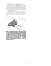
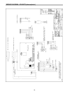
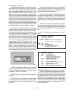
WIRING DIAGRAM KEY
PINK CONNECTOR BLUE CONNECTOR
Fig. # RP8096
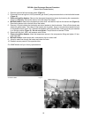
*If required by Local Code, install at this location.
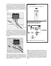
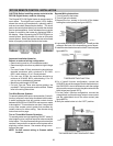
Fig. #2353
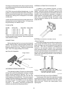
For 120 V input power to the unit, connect the black
wire to the “L1” or hot leg of the power supply. Connect
the white wire to the “L2” or neutral leg of the power
supply. Attach the wire nut to the red wire. There should
be no connection to the red wire for 120V operation. For
Low NOx pool heaters wire nut each red wire indepen-
dently.
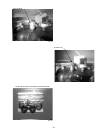
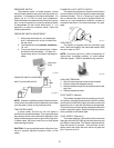
Fig. #9240
For 240 V input power to the unit, connect the black
wire to the “L1” or hot leg of the power supply. Connect
the red wire to the “L2” or second hot leg of the power
supply. Attach the wire nut to the white wire. There should
be no connection to the white wire for 240V operation.
for Low NOx pool heaters wire nut each white wire inde-
pendently.
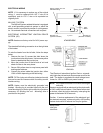
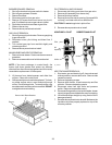
Fig. # 9241
Heater must be electrically grounded and bonded in
accordance with local codes, or, in the absence of local
codes, with the latest edition of the National Electrical
code, ANSI/NFPA 70. (Canada- Canadian Electrical
Code, CSA C22.1, Part 1 and Part 2.)
*
NOTE: Input power to the heater (120/240V) can be
supplied from the load (Pump) side of time clock or
directly from the switch/GFCI power source. If a remote
device (supplied by others) is to be used, the direct from
switch/GFCI power source method is preferred. When
a remote device is utilized, the direct power source will
allow the Safety Faults to be displayed including the
"REM", if the remote device is not in a "CALL FOR HEAT"
mode.
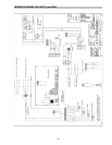
WIRING DIAGRAM MILLIVOLT UNITS
WITH MECHANICAL THERMOSTAT