


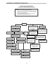

TUBE CLEANING PROCEDURE
Establish a regular inspection schedule, frequency
depending on local water condition and severity of
service. Do not let the tubes clog up solidly. Clean out
deposits over 1/16" in thickness.
The heater may be cleaned from the return header
side, without breaking pipe connections. It is prefer-
able, however, to remove both headers for better visibil-
ity through the tubes and to be sure the ground-up lime
dust does not get into the system.
Note that you do not remove the top panel or the
heater exchanger, generally.
After reaming, mount the wire brush in place of the
auger and clean out debris remaining in the tubes.
Another method is to remove the heat exchanger,
ream tubes and immerse heat exchanger in non-inhib-
ited de-scale solvent for severe scale build-up.
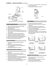
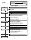
DESOOTING PROCEDURE
CAUTION: SOOT IS COMBUSTIBLE. EXERCISE
EXTREME CARE:
Soot will clog areas between fins and cause even-
tual tube failure. Any sign of soot at the base of the
burners or around the outer jacket indicates a need for
cleaning.
1. Remove top and flue collector from cabinet.
2. Remove "V" baffles from heat exchanger.
3. Remove burner drawer. (See burner tray removal).
4. Remove heat exchanger from the heater and wash
with a garden hose, making sure soot is removed
from spaces between fins.
5. Reverse above procedure to re-install.
NOTE: In extreme cases it may be necessary to do
steam cleaning at the local car wash. DO NOT
WIREBRUSH.
COMBUSTION CHAMBER REMOVAL
To remove combustion chamber, you must first
have removed the heat exchanger. Unbolt metal com-
bustion chamber retainer from top and remove combus-
tion chamber panels individually.
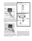
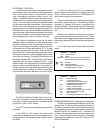
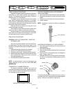
REFRACTORY PANELS TOP VIEW
Fig. #RP 8155.0
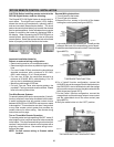
Extension Pieces (2) Auger with Carbide Tip Wire Brush
Fig. # 8154.0
29
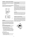
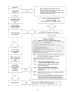
CONTROL IMMERSION WELL REPLACEMENT
(Millivolt and ASME)
1. Shut water off to heater and drain heat exchanger.
2. Remove access panel on water connection side of
heater.
3. Remove old control well with bushing and sleeve.
4. Install in header.
NOTE: Installation in plastic should be hand tight plus
1/2 turn.
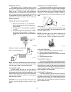
Well Assembly
Fig. #2010
UNITHERM GOVERNOR (U.G.) REPLACEMENT
1. Shut water, gas and electricity off, close valves and
relieve pressure.
2. Drain heat exchanger.
3. Remove retainer plug located next to the outlet pipe
connection.
4. Remove old U.G. from retainer plug. It is snapped in
place. Snap in new U.G.
5. Reinstall retainer plug, taking care to lubricate gas-
ket with a non-petroleum based grease such as
AquaLube.
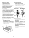
Retainer Plug
U.G.
Spring
Gasket
Fig. #2011
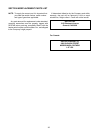
To test the operation of the Unitherm Governor, place in
hot water (over 100°F) and watch for movement against
spring. If there is no movement, replace unit.