


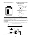
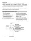
Heater must be located so that any water leaks will not
damage the structure of adjacent area. PVC pipe may
be glued directly into header unions.
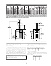
FLOW RATES
MODEL PIPE SIZE MIN.GPM *MAX.GPM
185 1-1/4"-1-1/2" - 2 20 125
265 1-1/4"-1-1/2" - 2 25 125
335 1-1/4"-1-1/2" - 2 35 125
405 1-1/4"-1-1/2" - 2 40 125
*When flow rates exceed maximum GPM an external
auxiliary bypass valve is required. See external bypass
valve section for details.
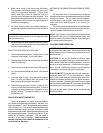
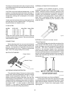
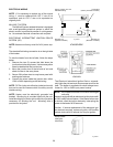
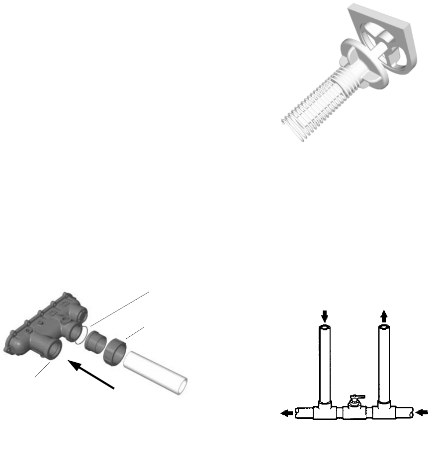
CONNECTIONS
Before attaching the 2-inch unions to the inlet/outlet
header, make sure the o-rings are properly seated in the
grooves. Use AquaLube or equivalent non-petroleum
based lubricant on the o-ring. Tighten the unions hand
tight. Glue PVC piping directly to the unions.
INLET/OUTLET HEADER
Flange Gasket
Fig. #2002.1
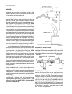
UNITHERM GOVERNOR OPERATION
The patented Unitherm Governor is a thermostatic
mixing valve specifically designed to maintain constant
heater internal temperature between 105° to 115°F
despite continually changing flow rates from the filter
and changing pool temperatures. This narrow range is
needed to prevent damaging condensation on the burn-
ers which will occur if the heater runs for any length of
time below 100°F. It is also needed to inhibit scale
formation in the tubes by maintaining temperatures
well below accelerated scaling temperatures.
16
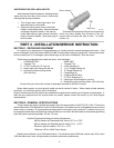
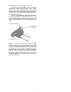
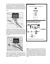
INTERNAL AUTOMATIC BY-PASS VALVE
In addition to the Unitherm Governor, a built-in
automatic by-pass valve is provided in the in/out
header. While the Unitherm Governor responds to the
changes in water temperature in the heater, the internal
by-pass valve automatically responds to changes in
water pressure in the piping system. Proper amount of
water flow is maintained through the heater under
varying pressures dictated by the conditions of the
pump and filter.
Fig.#2003
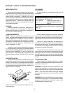
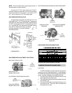
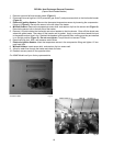
EXTERNAL AUXILIARY BYPASS VALVE
(Where Required)
An auxiliary bypass valve should be used when flow
rates exceed 125 GPM (usually a high performance
pump size larger than two horsepower will exceed this
flow rate). This valve is required to complement the
function of the automatic bypass valve, particularly
when starting the heater in winter or early spring when
the spa or pool temperature is down below 50°F. It also
serves to eliminate needless pressure drop through the
heater and accompanying reduction in the flow rate to
the spa jets, etc.
From Heater To Heater
To Pool From Pool
AUXILLARY BYPASS VALVE
(DO NOT USE GATE VALVE)
Fig. # 8150.0s
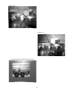
AUXILIARY BYPASS VALVE ADJUSTMENT
To set bypass: With clean filter, adjustment is made
by feeling the inlet and outlet pipes at the heater. Outlet
pipes should be slightly warmer than inlet and comfort-
able to the touch. If pipe is hot, close bypass; if cold,
open bypass.
Plumbing from the heater back to the pool must not have
any valves or restriction that could prevent flow when the
pump is operating.
CAUTION: A source of additional heated water, i.e. solar
systems, must be connected to the heater outlet pipe. If
this is connected to the heater inlet, incorrect pool water
temperature readings will be displayed on the heater
control panel.
Header Flange
Inlet