


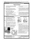

12"
Minimu
m
12"
M
inimum
4"
Minimum
HEATER
Sheet Metal
24 Gauge
SECTION 3 / INSTALLATION INSTRUCTIONS
10
IMPORTANT NOTICE
These instructions are intended for the use of quali-
fied personnel only, specifically trained and experienced
in the installation of this type of heating equipment and
related system components. Installation and service
personnel may be required by some states to be licensed.
If your state is such, be sure your contractor bears the
appropriate license. Persons not qualified shall not
attempt to fix this equipment nor attempt repairs accord-
ing to these instructions.
WARNING:
Improper installation, adjustment, alteration,ser-
vice or maintenance may damage the equipment,
create a hazard resulting in asphyxiation, explosion or
fire, and will void the warranty.
CODE REQUIREMENTS
NOTE: The heater should not be located in an area
where possible water leakage will result in damage to
the area adjacent to the appliance or to the structure.
When such locations cannot be avoided, it is recom-
mended that a suitable drain pan, adequately drained,
be installed under the appliance. The pan must not
restrict combustion air flow.
Installation must be in accordance with local codes,
or, in the absence of local codes, with the latest edition
of the National Fuel Gas Code, ANSI Z223.1 and National
Electrical Code, ANSI/NFPA 70, and for Canada, the
latest edition of CAN/CGA-B149.1 and B149.2, and
Canadian Electrical Code, CSA C22.1 Part 1 and Part
2.
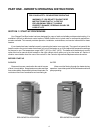
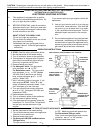
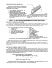
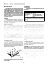
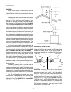
BASE INSTALLATION
Heater must be mounted on a level base, such as
cement slab, cement blocks or other non-combustible
surface. An optional non-combustible base is available
for all models. An alternative method for providing a base
for combustible floors is illustrated below. Heaters must
not be installed on carpeting.
Fig. # 8148.1
Utilize hollow concrete cinder blocks, align holes and
leave ends open.
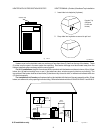
CLEARANCES
ALL HEATERS
For clearances from combustible surfaces, see the
chart below.
CLEARANCE FROM COMBUSTIBLE CONSTRUCTION
INDOOR INSTALLATIONS:
Top*(Drafthood) - 30" Back - 6"
Front - Alcove Right Side-(Water Side) 12"
Vent - 6" Left Side-(Opposite Water
side) 6"
OUTDOOR INSTALLATION:
Top* (Stackless top or outdoor stack) - Unobstructed
Back - 6"
Side - 6"
*Clearance from top of vent terminal.
When installed according to the listed minimum
clearances from combustible construction materials, the
Raypak pool heaters can still be serviced without remov-
ing permanent structural construction around the heater.
However for ease of servicing, we recommend a
clearance of at least 24" in the front, and at least 18" on
the water connection side. This will enable the heater to
be serviced in its installed location, that is, without
movement or removal of the heater.
Clearances less than these (6" minimum), may
require removal of the heater to service either the heat
exchanger or the burner tray. In either case, the heater
must be installed in a manner that will enable the heater
to be serviced without removing any structure around the
heater.
OUTDOOR HEATERS
These heaters are design certified for outdoor
installation, when equipped with the approved tops des-
ignated for outdoor use.
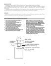
WARNING: The heater shall not be located in an area
where water sprinklers, or other devices, may cause
water to spray through the cabinet louvers and into the
heater. This could cause internal rusting or damage
some electrical components, and this would void the
warranty.
WARNING: Do not install within 3 feet of a heat pump or
an outdoor condensing unit. Strong air intake from these
equipment can disturb the combustion process and
cause damage or personal injury.