


VENT PIPING
WARNING:
Indoor boilers require a drafthood that must be
connected to a vent pipe and properly vented to the
outside. Failure to follow this procedure can cause fire
or fatal carbon monoxide poisoning.
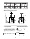
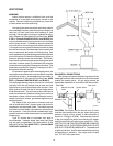
Vent piping the same size as the draft hood outlet is
recommended, however, when the total vent height is at
least ten (10) feet (draft hood relief opening to vent
terminal), the vent pipe size may be reduced as speci-
fied in Chapter 10 of the National Fuel Gas Code, ANSI
Z 223.1. (Canada-CAN/CGA-B149.1 and B149.2) As
much as possible avoid long horizontal runs of vent pipe
and too many elbows. If installation requires horizontal
non-vertical runs, the vent pipe must have a minimum of
1/4 inch per foot rise and should be supported at not less
than five foot intervals. Plumbers tape, criss-crossed, will
serve to space both horizontal and vertical piping. Gas
vents supported only by the flashing and extending above
the roof more than five feet should be securely guyed or
braced to withstand snow and wind loads. We recom-
mend use of insulated vent pipe spacer through the roofs
and walls. Another option for installation that requires
horizontal runs is using the D-2 powervent kit option. The
powervent is certified for catagory III venting up to 40 ft.
equivalent 4" diameter venting.
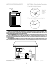
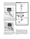
For protection against rain or blockage by snow, the
vent pipe must terminate with a vent cap which complies
with the local codes or, in the absence of such codes, to
the latest edition of the National Fuel Gas Code, ANSI
Z223.1. (Canada-CAN/CGA-B149.1 and B149.2)
The discharge opening must be a minimum of two feet
vertically from the roof surface and at least two feet
higher than any part of the building within ten feet. Vent
stack shall be at least five feet in vertical height above
the drafthood outlet. The vent cap location shall have a
minimum clearance of 4 feet horizontally from, and in no
case below, unless a 4-foot horizontal distance is main-
tained, from electric meters, gas meters regulators and
relief equipment.
The weight of the vent stack or chimney must not
rest on heater draft hood. Support must be provided in
compliance with applicable codes. The heater top and
draft hood must be readily removable for maintenance
and inspection. Vent pipe should be adequately sup-
ported to maintain proper clearances from combustible
construction.
Type "B" double wall or equivalent vent pipe is
recommended. However single wall metal vent pipe
may be used as specified in the latest edition of the
National Flue Gas Code ANSI Z 223.1. (Canada-CAN/
CGA-B149.1 and B149.2)
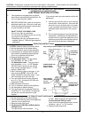
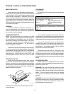
Fig. #RP 8119.2
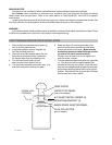
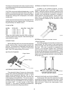
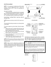
GAS SUPPLY CONNECTIONS
Gas piping must have a sediment trap ahead of the
heater gas controls, and a manual shut-off valve located
outside the heater jacket. All gas piping should be
tested after installation in accordance with local codes.
Gas Inlet Gas Valve
Manual Shut-Off Heater Jacket
Valve
Sediment Trap
Union
Fig. #8090.0
CAUTION: The heater and its manual shut off valve
must be disconnected from the gas supply during any
pressure testing of that system at test pressures in
excess of 1/2 psig (3.45 KPA). Dissipate test pressure
in the gas supply line before reconnecting the heater
and its manual shut off valve to gas supply line. FAIL-
URE TO FOLLOW THIS PROCEDURE MAY DAMAGE
THE GAS VALVE. OVER PRESSURED GAS VALVES
ARE NOT COVERED BY WARRANTY. The heater and
its gas connections shall be leak tested before placing
the appliance in operation. Use soapy water for leak
test. DO NOT use open flame.
14