


17
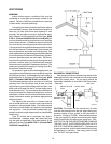
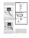
PRESSURE RELIEF VALVE INSTALLATION
To conform to local building codes, it may be
necessary to install a pressure relief valve. A 3/4"
pressure relief valve having a capacity equal to BTU/HR
output of the model to be installed is recommended for
this appliance. The maximum acceptable pressure re-
lief valve setting is 125 psi.
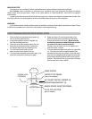
A 3/4" NPT connection is provided in the inlet/outlet
header for installation of a pressure relief valve. The
valve shall be installed in a vertical position. Do not over
tighten. Install pressure relief valve hand tight plus 1/2
turn.
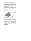
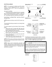
Pressure Relief Valve
PRV Discharge
Connection
Inlet/Outlet Header
Fig. #2004
NOTE: To avoid water damage or scalding due to valve
operation, drain pipe must be connected to valve outlet
and run to a safe place of discharge. Drain pipe must be
the same size as the valve discharge connection
throughout its entire length and must pitch downward
from the valve. No shutoff valve shall be installed
between the relief valve and the drain line. Valve lever
should be tripped at least once a year to ensure that
waterways are clear.