


ELECTRICAL WIRING
NOTE: If it is necessary to replace any of the original
wiring, it must be replaced with 105° C wire or its
equivalent, and /or 150° C wire or its equivalent as
originally built.
MILLIVOLT SYSTEM
The Millivolt System residential heater is equipped
with a self-generating electrical system in which the
electric current is provided by means of a pilot genera-
tor. No external electrical connections are required.
ELECTRONIC INTERMITTENT IGNITION DEVICE
SYSTEM (IID)
NOTE: Heaters are factory wired for 240V power sup-
ply.
The standard field wiring connection is on the right side
of the heater.
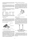
To wire the heater from the left side, follow the steps
below:
1. Remove the two (2) screws that hold down the
junction box to the sway brace. Untie excess yellow
wires located behind the junction box.
2. Move the junction box to the left side of unit and
attach the box to the sway brace.
3. Secure 24V yellow wires to sway brace panel with
existing wire retainers.
4. Connect the wires inside the junction box, either
120V or 240V depending on the field wiring.
NOTE: 7/8" Dia. holes not utilized on jacket and control
box can be used for fireman switch or auxiliary control
interface wiring.
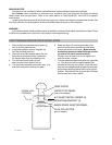
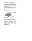
NOTE: Heater must be electrically grounded and
bonded. Bonding lug is provided loose with the unit.
Install bonding lug on lower right or left side of jacket as
necessary for bonding the unit. Mounting hole is
provided on the jacket.
20
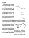
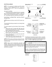
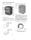
Option Location For Left
Side Field Wiring
Sway
Brace
Bonding Lug
(Standard Location)
Bonding Lug
(Optional Location)
Fig. # 9030.1
Control Box
(Factory Mounted Location)
The Electronic Intermittent Ignition Device automati-
cally lights the pilot and main burners upon a call for the
heat. The heater is supplied with a dual voltage trans-
former for 120V or 240V input power hookup.
NOTE: IID Propane Units and IID Low NOx natural gas
units only
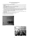
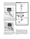
Heater is equipped with an electronic ignition device with
a 100% safety lockout feature. If the heater fails to start
or lockout, reset the ignition device by interrupting the
power to the heater for 60 seconds.
Caution: If service replacement of the electronic igni-
tion device is required, replace only with a 100% safety
lockout device with 90 second trial for pilot ignition.
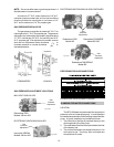
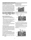
HONEYWELL
IGNITION
CONTROL
Fig. # 8929.1
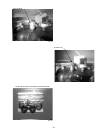
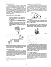
LOW NOx
ATMOSPHERIC