


Agilent N518xA, E8663B, E44x8C, and E82x7D Signal Generators Programming Guide 193
Creating and Downloading Waveform Files
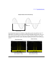
Waveform Structure
Waveform Structure
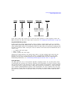
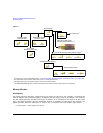
To play back waveforms, the signal generator uses data from the following three files:
•File header
•Marker file
•I/Q file
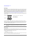
All three files have the same name, the name of the I/Q data file, but the signal generator stores
each file in its respective directory (headers, markers, and waveform). For information on file
extractions, see “Commands for Downloading and Extracting Waveform Data” on page 204.
File Header
The file header contains settings for the ARB modulation format such as sample rate, marker polarity,
I/Q modulation attenuator setting and so forth. When you create and download I/Q data, the signal
generator automatically creates a file header with all saved parameters set to unspecified. With
unspecified header settings, the waveform either uses the signal generator default settings, or if a
waveform was previously played, the settings from that waveform. Ensure that you configure and save
the file header settings for each waveform.
NOTE If you have no RF output when you play back a waveform, ensure that the marker RF
blanking function has not been set for any of the markers. The marker RF blanking function
is a header parameter that can be inadvertently set active for a marker by a previous
waveform. To check for and turn RF blanking off manually, refer to “Configuring the
Pulse/RF Blank (Agilent MXG)” on page 277 and “Configuring the Pulse/RF Blank
(ESG/PSG)” on page 277.
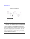
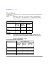
Marker File
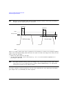
The marker file uses one byte per I/Q waveform point to set the state of the four markers either on
(1) or off (0) for each I/Q point. When a marker is active (on), it provides an output trigger signal to
the rear panel EVENT 1 connector (Marker 1 only) or and the AUX IO, event 2 connector pin
(Markers 1, 2, 3, or 4), that corresponds to the active marker number. (For more information on
active markers and their output trigger signal location, refer to your signal generator’s User’s Guide.)
Because markers are set at each waveform point, the marker file contains the same number of bytes
as there are waveform points. For example, for 200 waveform points, the marker file contains 200
bytes.
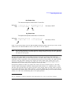
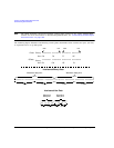
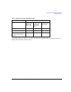
Although a marker point is one byte, the signal generator uses only bits 0–3 to configure the
markers; bits 4–7 are reserved and set to zero. The following example shows a marker byte.