


Agilent N518xA, E8663B, E44x8C, and E82x7D Signal Generators Programming Guide 155
Programming the Status Register System
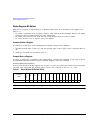
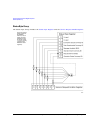
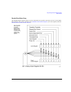
Status Byte Group
Status Byte Register
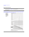
Service Request Enable Register
The Service Request Enable Register lets you choose which bits in the Status Byte Register trigger a
service request.
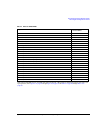
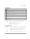
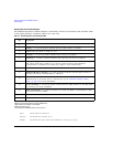
Table 4-3 Status Byte Register Bits
Bit Description
0,1 Unused. These bits are always set to 0.
2 Error/Event Queue Summary Bit. A 1 in this bit position indicates that the SCPI error queue is not empty. The SCPI
error queue contains at least one error message.
3 Data Questionable Status Summary Bit. A 1 in this bit position indicates that the Data Questionable summary bit has
been set. The Data Questionable Event Register can then be read to determine the specific condition that caused this
bit to be set.
4 Message Available. A 1 in this bit position indicates that the signal generator has data ready in the output queue.
There are no lower status groups that provide input to this bit.
5 Standard Event Status Summary Bit. A 1 in this bit position indicates that the Standard Event summary bit has been
set. The Standard Event Status Register can then be read to determine the specific event that caused this bit to be set.
6 Request Service (RQS) Summary Bit. A 1 in this bit position indicates that the signal generator has at least one
reason to require service. This bit is also called the Master Summary Status bit (MSS). The individual bits in the Status
Byte are individually ANDed with their corresponding service request enable register, then each individual bit value is
ORed and input to this bit.
7 Standard Operation Status Summary Bit. A 1 in this bit position indicates that the Standard Operation Status
Group’s summary bit has been set. The Standard Operation Event Register can then be read to determine the specific
condition that caused this bit to be set.
Query: *STB?
Response: The decimal sum of the bits set to 1 including the master summary status bit (MSS) bit 6.
Example: The decimal value 136 is returned when the MSS bit is set low (0).
Decimal sum = 128 (bit 7) + 8 (bit 3)
The decimal value 200 is returned when the MSS bit is set high (1).
Decimal sum = 128 (bit 7) + 8 (bit 3) + 64 (MSS bit)
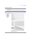
*SRE <data> <data> is the sum of the decimal values of the bits you want to enable except bit 6. Bit 6
cannot be enabled on this register. Refer to Figure 4-1 on page 140 through Figure 4-8 on
page 147.
Example: To enable bits 7 and 5 to trigger a service request when either corresponding status group
register summary bit sets to 1, send the command *SRE 160 (128 + 32).
Query: *SRE?
Response: The decimal value of the sum of the bits previously enabled with the *SRE <data> command.