


34
_ _ _ _
I and Q out I and Q are used in conjunction with I and Q to
provide a balanced baseband stimulus. Balanced signals
are signals present in two separate conductors that are
symmetrical about the common mode offset, and are
opposite in polarity [180 degrees out of phase].
These female BNC connectors are provided only on
signal generators with Option 601 or 602. If you configure
your signal generator with Option 1EM, these inputs are
relocated to rear panel SMB connectors.
LF output Outputs the internally-generated LF source. Outputs 0 to
2.5 V
peak
into 50 ohms, or 0 to 5 V
peak
into high
impedance. [BNC, front panel]
Pattern trigger input Accepts CMOS
1
signal to trigger internal pattern or frame
generator to start single pattern output. Minimum pulse
width 100 ns. The damage levels are –0.5 to +5.5 V.
[BNC, rear panel]
Q input Accepts a Q input for I/Q modulation. Nominal input
impedance 50 or 600 ohms, damage levels are 1 V
rms
and 10 V
peak
. [BNC, front panel]
RF output Nominal output impedance 50 ohms.
[type-N female, front panel]
Sweep output Generates output voltage, 0 to +10 V when signal
generator is sweeping. Output impedance < 1 ohm, can
drive 2000 ohms. [BNC, rear panel]
Symbol sync input The CMOS
1
compatible symbol sync connector accepts
an externally supplied symbol sync for digital modulation
applications. The expected input is a symbol clock signal.
It may be used in two modes. When used as a symbol
sync in conjunction with a data clock, the signal must be
high during the first data bit of the symbol. The signal
must be valid during the falling edge of the data clock
signal and may be a single pulse or continuous. When
the symbol sync itself is used as the [symbol] clock, the
falling edge is used to clock the data signal.
The maximum clock rate is 50 MHz. The damage levels
are –0.5 to +5.5 V. [BNC, front panel]
This female BNC connector is provided on signal
generators with Option 601 or 602. On signal generators
with Option 1EM, this input is relocated to a rear panel
SMB connector.
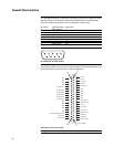
Symbol sync output Outputs CMOS
1
symbol clock for symbol synchronization,
one data clock period wide. [Auxiliary I/O connector,
rear panel]
Trigger input Accepts CMOS
1
signal for triggering point-to-point in
manual sweep mode, or to trigger start of LF sweep.
the damage levels are –0.5 to +5.5 V. [BNC, rear panel]
Trigger output Outputs a TTL signal: high at start of dwell, or when
waiting for point trigger in manual sweep mode; low
when dwell is over or point trigger is received, high or
low 2 µs pulse at start of LF sweep. [BNC, rear panel]
1. Rear panel inputs and outputs are 3.3 V CMOS, unless indicated otherwise. CMOS inputs will accept 5 V CMOS, 3 V CMOS, or TTL voltage levels.
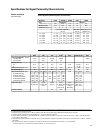
General Characteristics