


27
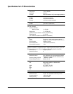
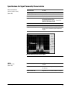
Multiframe output data generation
Coding scheme MCS-1: uplink and downlink, MCS-5: uplink and downlink,
MCS-9: uplink and downlink, E-TCH/F43.2
Data PN9 or PN15
The selected data sequence is fully coded
continuously across the RLC data blocks according to
MCS-1, MCS-5, MCS-9 or E-TCH/F43.2. An independent
version of the selected data sequence is coded across the
unused RLC/MAC header fields [The CPS header field is
as defined in GSM 04.60 V8.50].
Frame structure 52-frame multi-frame structure for EDGE/EGPRS channel
as per ETSI TS 100 909, 3GPP TS 05.03, V8.9.0, 2000-11
[release 1999]. [Coding is done on frames 0-11, 13-24,
26-37, 39-50 on a 52 PDCH multi-frame. Frame 25 and
51 are idle [RF blanked].]
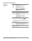
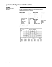
Adjacent timeslots
Data Coded MCS-1, MCS-5 or MCS-9 with continuous PN9 or
PN15 sequence data payload.
Uncoded PN9, PN15.
Note: Maximum of 4 timeslots can be turned on with
EDGE/EGPRS multi-frame coded data.
Frame structure EDGE/EGPRS PDCH multi-frame.
Repeating EDGE frame.
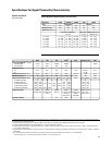
Multiframe measurements
1
EDGE measurement modes
Static sensitivity BER/BLER at user-specified power level measured;
based on bit errors in total unencoded data, and block
errors in coded channels.
Sensitivity search Automatically finds the input level [sensitivity] that causes
BER/BLER user-specified BER [uncoded] or BER [coded].
EDGE measurement results Erased data block count/rate for coded channel
[MCS-1, MCS-5 or MCS-9].
Total data block count for coded channel
[MCS-1, MCS-5 or MCS-9].
Payload bit error count/rate for raw BER.
Total burst count for raw BER. Data block count which
contains residual bit errors and bit error count.
Downlink error reporting
1. Measurements also require Option 300.
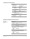
Specifications for Signal Personality Characteristics
EDGE/EGPRS
[real-time mode]
[Option 402]