


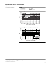
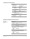
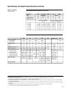
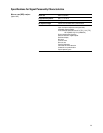
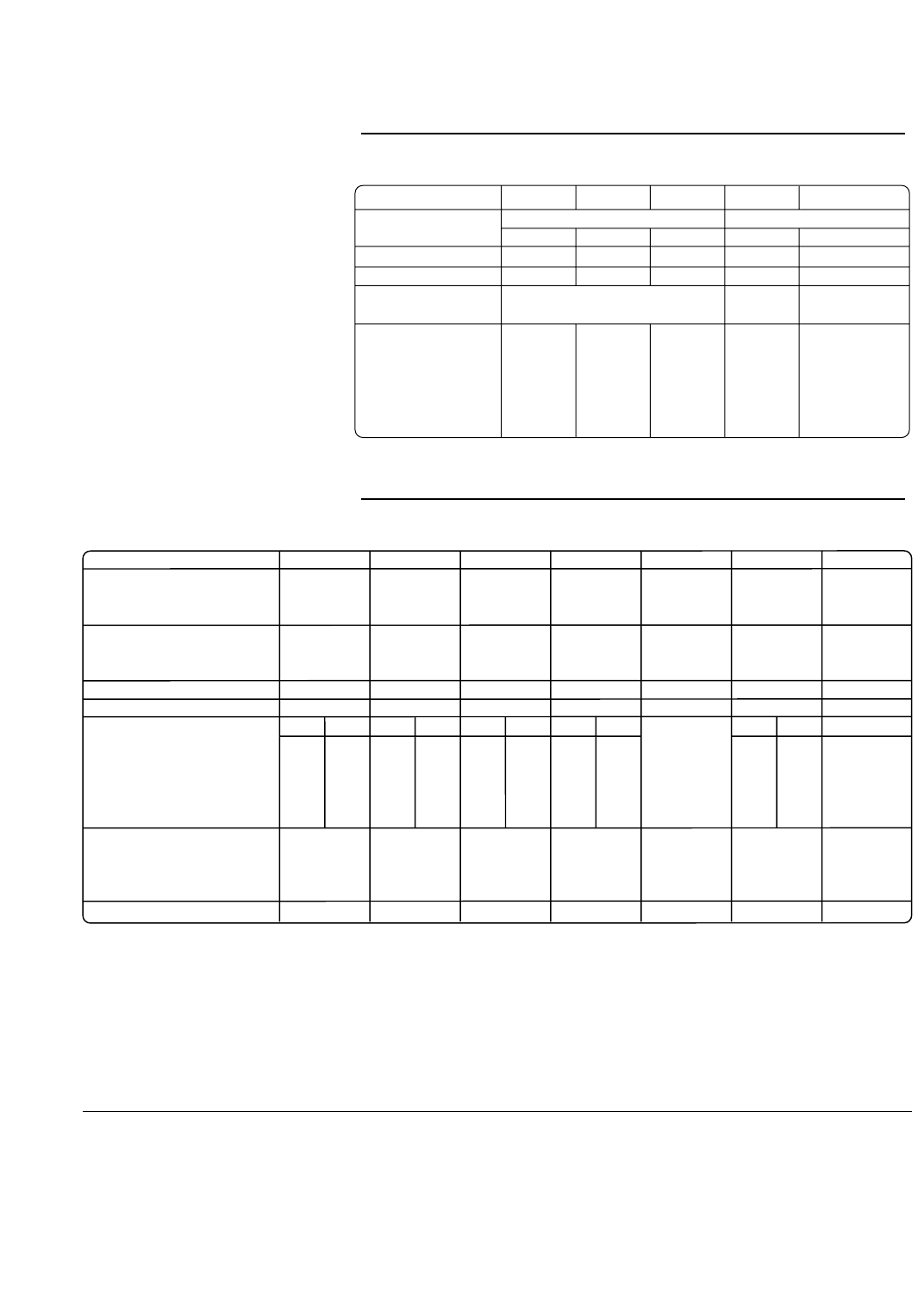
25
Modulation QPSK π/4DQPSK 16QAM 2FSK GMSK
Filter Root Nyquist Gaussian
Filter factor [a or B
b
T] 0.25 0.25 0.25 0.5 0.5
Modulation index N/A N/A N/A 0.5 N/A
Symbol rate [Msym/s] 4 4 4 1 1
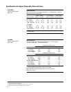
Error vector magnitude
3, 4
Shift error
3, 4
Global phase error
3, 4
[% rms] [% rms] [degrees rms]
fc = 1 GHz 1.1 (0.7) 1.1 (0.7) 1.0 (0.6) 1.3 (0.8) 0.4 (0.2)
fc = 2 GHz 1.2 (0.8) 1.2 (0.8) 1.0 (0.6) 1.4 (0.9) 0.5 (0.3)
fc = 3 GHz 1.6 (1.0) 1.6 (1.0) 1.5 (0.9) 1.8 (1.0) 0.7 (0.4)
fc = 4 GHz 2.5 (1.4) 2.5 (1.3) 3.3 (1.9) 3.3 (2.0) 1.0 (0.6)
fc = 5 GHz 1.5 (1.0) 1.5 (1.0) 1.2 (0.8) 1.8 (1.2) 0.6 (0.3)
fc = 6 GHz 1.8 (1.2) 1.8 (1.2) 1.4 (1.0) 2.0 (1.4) 0.8 (0.4)
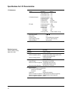
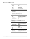
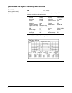
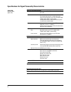
NADC PDC PHS TETRA
4
DECT GSM DCS, PCS EDGE
Error vector magnitude
6, 4
[% rms]
Low EVM mode 1.2 (0.7) 1.2 (0.7) 0.9 (0.5) 0.8 (0.5) 1.2 (0.6)
Low ACP mode (1.2) (0.9) (0.6) (1.0)
Global phase error
2
rms N/A N/A N/A N/A N/A 0.6 (0.3) N/A
pk 1.9 (1.0)
Deviation accuracy
2
[kHz, rms] N/A N/A N/A N/A 2.5 (1.1) N/A N/A
Channel spacing [kHz] 30 25 300 25 1728 200 200
Adjacent channel power
2
[ACP] Cont. Burst Cont. Burst Cont. Burst Cont. Burst N/A Cont. Burst N/A
(Low ACP mode, dBc)
at adjacent channel
7
(–35) (–34) – – – – (–70) (–63) (–37) (–37)
at 1st alternate channel
7
(–80) (–79) (–74) (–74) (–81) (–76) (–81) (–80) (–71) (–70)
at 2nd alternate channel
7
(–84) (–83) – – (–82) (–79) (–82) (–82) (–84) (–81)
at 3rd alternate channel
7
(–85) (–84) (–82) (–82) – – (–83) (–83) (–85) (–81)
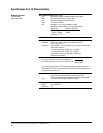
Support burst types Custom Custom Custom Custom Custom Custom, normal
up/down TCH up/down TCH TCH, sync up control 1 & 2, dummy B 1 & 2, Fcorr, sync,
up Vox up normal, traffic B, dummy, access
down normal, low capacity
Scramble capability Yes Yes
1. This level of performance can be attained using the external I/Q inputs, provided the quality of the baseband signal meets or exceeds that of the ESG baseband generator.
2. Parentheses denote typical performance.
3. Specifications apply at power levels ≤ +4 dBm [≤ +5 dBm for Option 506, and ≤ +8 dBm for Option UNB] with default scale factor of I/Q outputs.
4. Valid after executing I/Q calibration and maintained within +/- 5 °C of the calibration temperature.
5. ACP for TETRA is measured over a 25 kHz bandwidth, with an 18 kHz root raised cosine filter. Low ACP mode is valid at power levels ≤ –1 dBm [≤ 1 dBm for Option 506
and ≤ +4 dBm for Option UNB].
6. Specifications apply for the symbol rates, filter, filter factors [a or BbT] and default scaling factor specified for each standard, and at power levels ≤ +7 dBm [≤ +10 dBm for
Option UNB].
7. The “channel spacing” determines the offset size of the adjacent and alternate channels: Adjacent channel offset = 1 x channel spacing,
1st alternate channel = 2 x channel spacing, 2nd alternate channel = 3 x channel spacing, etc.
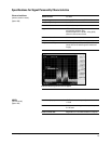
Custom digitally modulated signals [real-time mode]
1, 2
Internal modulation using real-time TDMA personalities [Option 402]
2
Specifications for Signal Personality Characteristics
Custom modulation
[real-time mode]