


32
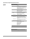
Data clock input The CMOS
1
compatible data clock connector
accepts an externally supplied data-clock input for
digital modulation applications. The expected input is a
bit clock signal where the falling edge is used to clock
the data and symbol sync signals.
The maximum clock rate is 50 MHz. The damage levels
are –0.5 to +5.5 V.
This female BNC connector is provided on signal
generators with Option 601 or 602. On signal generators
with Option 1EM, this input is relocated to a rear panel
SMB connector.
Data clock output Relays a CMOS
1
bit clock signal for synchronizing
serial data. [Auxiliary I/O connector, rear panel]
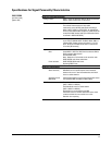
Data input The CMOS
1
compatible data connector accepts an
externally supplied data input for digital modulation
applications. CMOS high is equivalent to a data 1 and
a CMOS low is equivalent to a data 0.
The maximum data rate is 50 Mb/s. The data must be
valid on the data clock falling edges [normal mode] or
the symbol sync falling edges [symbol mode]. The
damage levels are –0.5 to +5.5 V.
This female BNC connector is provided on signal
generators with Option 601 or 602. On signal generators
with Option 1EM, this input is relocated to a rear panel
SMB connector.
Data output Outputs serial data from the internal data generator or
the externally supplied signal at the data input. CMOS
1
signal. [Auxiliary I/O connector, rear panel]
Event 1 output In real-time mode, outputs pattern or frame
synchronization pulse for triggering or gating external
equipment. May be set to start at the beginning of a
pattern, frame, or timeslot and is adjustable to within
± one timeslot with one bit resolution.
In arbitrary waveform mode, this connector outputs the
timing signal generated by marker 1. [BNC, rear panel]
Event 2 output In real-time mode, outputs data enabled signal for gating
external equipment. Applicable when external data is
clocked into internally generated timeslots. Data is
enabled when signal is low.
In arbitrary waveform mode, this connector outputs the
timing signal generated by marker 2. [BNC, rear panel]
Event 3 output In arbitrary waveform mode, this connector outputs the
timing signal generated by marker 3. [Auxiliary I/O
connector, rear panel]
Event 4 output In arbitrary waveform mode, this connector outputs the
timing signal generated by marker 4. [Auxiliary I/O
connector, rear panel]
1. Rear panel inputs and outputs are 3.3 V CMOS, unless indicated otherwise. CMOS inputs will accept 5 V CMOS, 3 V CMOS, or TTL voltage levels.
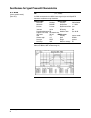
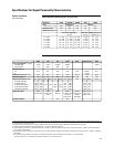
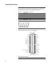
General Characteristics