


33
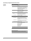
External 1 input This BNC input connector accepts a ±1 V
peak
signal for
AM, FM, pulse, burst, and phase modulation. For all
these modulations, ±1 V
peak
produces the indicated
deviation or depth. When ac-coupled inputs are selected
for AM, FM, or phase modulation and the peak input
voltage differs from 1 V
peak
by more than 3%, the hi/lo
annunciator light on the display. The input impedance is
50 ohms and the damage levels are 5 V
rms
and 10 V
peak
.
If you configure your signal generator with Option 1EM,
this input is relocated to a female BNC connector on the
rear panel.
External 2 input This BNC input connector accepts a ±1 V
peak
signal for
AM, FM, phase modulation, and pulse modulation. With
AM, FM, or phase modulation, ±1 V
peak
produces the
indicated deviation or depth. With pulse modulation,
+1 V is on and 0 V is off. When ac-coupled inputs are
selected for AM, FM, or phase modulation, and the peak
voltage differs from 1 V
peak
by more than 3%, the hi/lo
annunciator light on the display. The input impedance is
50 ohms and the damage levels are 5 V
rms
and 10 V
peak
.
If you configure your signal generator with Option 1EM,
this input is relocated to a female BNC connector on the
rear panel.
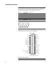
GPIB Allows communication with compatible devices.
[rear panel]
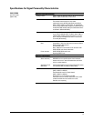
I input Accepts an I input either for I/Q modulation or for
wideband AM. Nominal input impedance 50 or 600 ohms.
Damage levels are 1 V
rms
and 10 V
peak
. [BNC, front panel]
I out and Q out
1
The I out and Q out connectors output the analog
components of I/Q modulation from the internal
baseband generator. The nominal output impedance of
these connectors are 50 Ω, DC-coupled. The damage
levels are > +3.5 V and < –3.5 V. The output signal levels
into a 50 Ω load are as follows:
• (O.5 V
peak
,), corresponds to one unit length of
the I/Q vector.
• (0.7 V
peak
), for peaks for p/4 DQPSK.
• (1.6 V
p-p
) maximum [Options 601, 602, 001, 002 only].
These female BNC connectors are provided on signal
generators with Option 601 or 602. On signal generators
with Option 1EM, these inputs are relocated to rear
panel SMB connectors.
1. Parentheses denote typical performance.
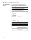
General Characteristics