EPSON Stylus Color 900 Revision C
Maintenance Lubrication and Adhesion 169
Table 6-6. Lubrication Points (continued)
No.
Lubricating Point
Amount
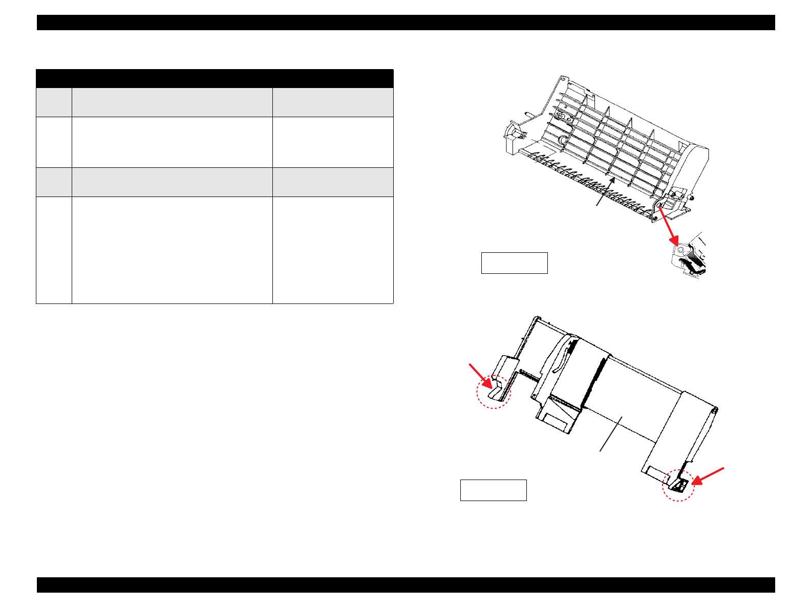
16 U-shape groves on the right and left edges of
the [Paper Guide Front Unit].
G-26 (
φ
1 x 5 mm, top and
bottom)
17 The surface of the [Shaft, CR]
NOTE: Do not apply lubricant to the [Shaft,
CR, Support].
O-8
18 Shaft hole of the [Combination Gear, 29.6,
29.6]
G-26 (
φ
1 x 5 mm)
19 The areas where the [Combination Gear,
29.6,29.6] and [Combination Gear,15.2,23.2]
come in contact with the [Mounting Plate
Assembly, Cap].
NOTE: Do not apply lubricant to the shaft
of the [Combination Gear, 15.2,
23.2] which joins with the hole in
the [Pump Assembly].
G-26 (
φ
1 x 5 mm)
G-26
[F ra m e , A S F ;B ]
[Hopper Assem bly, C]
G-26
G-26
Figure 6-8
Figure 6-9


