EPSON Stylus Color 900 Revision C
Disassembly and Assembly Disassembly Procedures 117
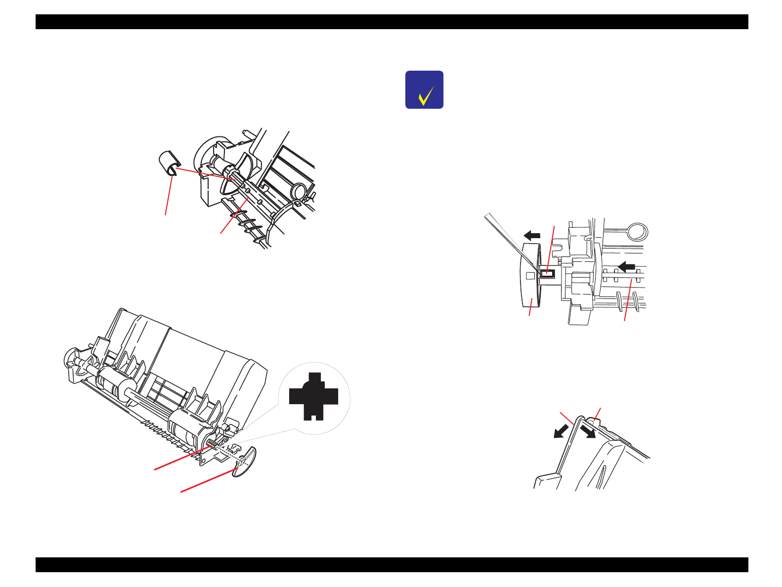
4.2.7.5.1 ASF Disassembly
1. Remove the ASF. (See Section 4.2.7.5.)
2. Remove the left shaft bushing located at the left end of the loading
(LD) roller shaft.
Figure 4-22. Left Bushing Removal
3. Remove the release hopper lever from the LD roller shaft.
Figure 4-23. Release Hopper Lever Removal
4. Shift the whole LD roller shaft to the left about 2 cm. Then, using
tweezers, remove the detection wheel by releasing the tab attaching
the detection wheel to the left end of the LD roller shaft.
Figure 4-24. Detection Wheel Removal
5. Release the peg fixing the hopper assembly to the ASF frame by the
top left. Then separate the hopper assembly and the ASF frame.
Figure 4-25.
Separating the Hopper Assembly from the ASF Frame
Bushing Fixing the Shaft
on the Left
LD Roller Shaft
S h a ft's S id e F a c
LD Roller Shaft
R elease Hopper Lever (R ight)
CHECK
POINT
When installing the shaft release hopper lever, pay
attention to the direction for installing it. However, the
lever does not fit in if the direction is wrong. Therefore,
referring to Figure 4-23, find the correct direction with
which you can push the release hopper lever without
force.
Fixing Tab
D etection W heel
LD Roller Shaft
Hopper Assem bly
ASF Frame


