EPSON Stylus Color 900 Revision C
Disassembly and Assembly Disassembly Procedures 108
4. Remove two screws securing the waste ink drain pad cover to the
lower case and remove it.
5. Disconnect two printhead control FFCs from the C265 main board.
6. Remove four large screws securing the printer mechanism to the
lower case, and remove the printer mechanism.
4.2.3 C265 Main Board Unit Removal
1. Remove the printer mechanism. (See Section 4.2.2.)
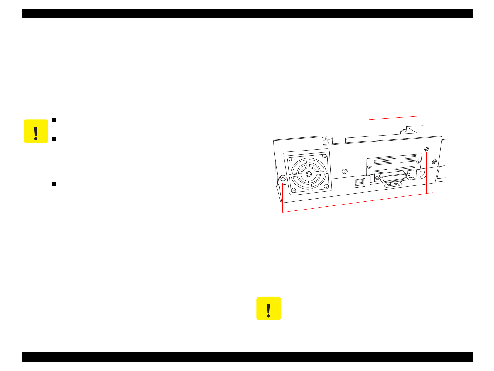
2. Remove four screws securing the rear case to the stay on the C265
Main board.
Figure 4-6. C265 Main Board Removal
3. Remove two screws securing the Type B interface cover to the
printer, and remove the rear case.
4. Disconnect two connectors CN5 and CN6 from the C265 Main
board and remove the C265 Main board unit.
CAUTION
After replacing the Waste Ink Pads, perform any
necessary adjustments. (See Table 4-1)
When installing the FFCs, remove the frame secured
by two screws before connecting the FFCs.
Otherwise, the FFCs will not be connected to the
connectors properly, and the printheads may be
damaged when voltage is applied.
When mounting the four screws, do not fasten them
excessively, or the tapped areas in the lower will be
damaged.
CAUTION
After removing/replacing the C265 Main Board,
perform any necessary adjustments. (See Table 4-1)
Screws securing the Rear Case
Screws securing the Type B I/F Cover


