


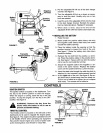

CHOKECONTROL
The choke control is located on the right side of the
dashboard and is operated manually. Details for the
choke operation are covered in the separate engine
manual packed with your unit. See figure 9.
LIGHT SWITCH
The head lamps are operated by pushing the light
switch located on the dashboard. The head lamps will
only operate when the engine is running. See figure 9.
AMMETER
The ammeter registers the rate of battery charge or
discharge. The ammeter will register on the discharg-
ing side with starting the engine. It should register on
the opposite side (charging) when the engine is run-
ning in the fast position until the battery is completely
charged. With a fully charged battery or with the
engine idling, the ammeter will not show a charge.
See figure 9.
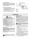
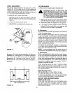
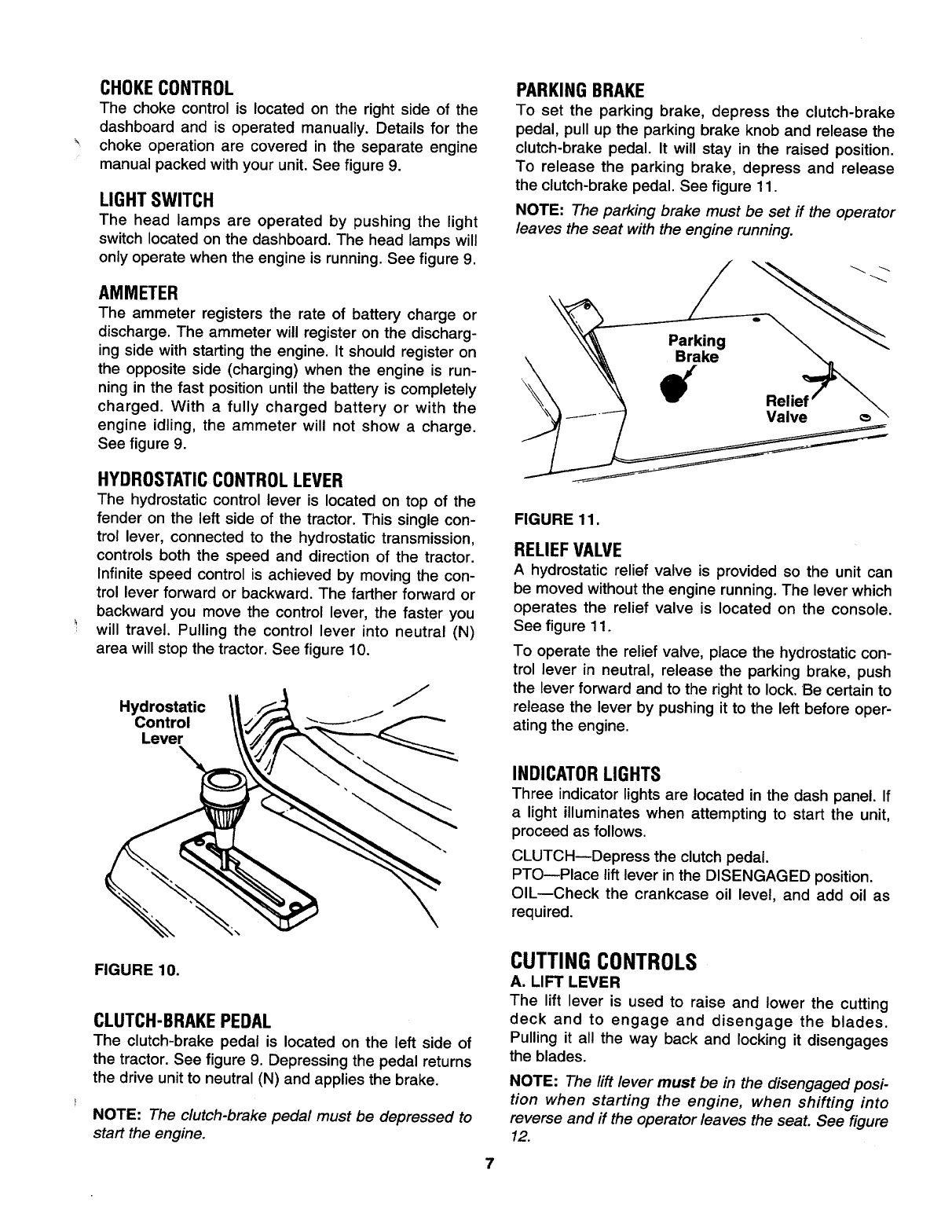
HYDROSTATICCONTROL LEVER
The hydrostatic control lever is located on top of the
fender on the left side of the tractor. This single con-
trol lever, connected to the hydrostatic transmission,
controls both the speed and direction of the tractor.
Infinite speed control is achieved by moving the con-
trol lever forward or backward. The farther forward or
backward you move the control lever, the faster you
will travel. Pulling the control lever into neutral (N)
area will stop the tractor. See figure 10.
Hydrostatic
Control
Lever
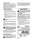
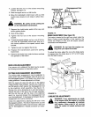
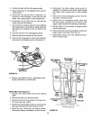
PARKING BRAKE
To set the parking brake, depress the clutch-brake
pedal, pull up the parking brake knob and release the
clutch-brake pedal. It will stay in the raised position.
To release the parking brake, depress and release
the clutch-brake pedal. See figure 11.
NOTE: The parking brake must be set if the operator
leaves the seat with the engine running.
FIGURE 11.
RELIEF VALVE
A hydrostatic relief valve is provided so the unit can
be moved without the engine running. The lever which
operates the relief valve is located on the console.
See figure 11.
To operate the relief valve, place the hydrostatic con-
trol lever in neutral, release the parking brake, push
the lever forward and to the right to lock. Be certain to
release the lever by pushing it to the left before oper-
ating the engine.
INDICATORLIGHTS
Three indicator lights are located in the dash panel. If
a light illuminates when attempting to start the unit,
proceed as follows.
CLUTCH--Depress the clutch pedal.
PTO--Place lift lever in the DISENGAGED position.
OIL--Check the crankcase oil level, and add oil as
required.
FIGURE 10.
CLUTCH-BRAKEPEDAL
The clutch-brake pedal is located on the left side of
the tractor. See figure 9. Depressing the pedal returns
the drive unit to neutral (N) and applies the brake.
NOTE: The clutch-brake pedal must be depressed to
start the engine.
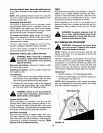
CUTTING CONTROLS
A. LIFT LEVER
The lift lever is used to raise and lower the cutting
deck and to engage and disengage the blades.
Pulling it all the way back and locking it disengages
the blades.
NOTE: The lift lever must be in the disengaged posi-
tion when starting the engine, when shifting into
reverse and if the operator leaves the seat. See figure
12.