


WHEEL ADJUSTMENT
The caster (forward slant of the king pin) and the
camber (tilt of the wheels out at the top) require no
adjustment. Automotive steering principles have been
used to determine the caster and camber on the trac-
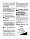
tor. The front wheels should toe-in 1/8 inch.
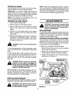
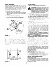
To adjust the toe-in, follow these steps.
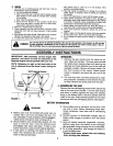
1. Remove the hex nut and lock washer, and drop
the end of the tie rod from the axle bracket. See
figure 17.
2. Loosen the hex jam nut on tie rod.
3. Adjust the tie rod assembly for correct toe-in.
Hex Jam
NutI
o Tie Rod _
End
FIGURE 17.
/
, Bracket
!,
\ /
Hex Nut
Lock Washer /
J.__j
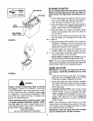
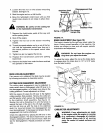
Dimension "B" should be approximately 1/8" less than
Dimension "A." See figure 18. To increase Dimension
"B," screw tie rod into tie rod end. To decrease
Dimension "B," unscrew tie rod from tie rod end.
Reassemble tie rod. Check dimensions. Readjust if
necessary.
Front
I °
4 (1/8" Less Than A)
i .I
I
FIGURE 18.
12
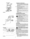
CUTTING BLADES
A. Removal for Sharpening or Replacement
&
WARNING: Be sure to disconnect and
ground the spark plug wire and remove
ignition key before working on the cutting
blade to prevent accidental engine start-
ing. Protect hands by using heavy gloves
or a rag to grasp the cutting blades.
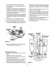
1. Remove the large bolt and lock washer which
holds the blade and adapter to the blade spindle.
2. Remove the blade and adapter from the spindle.
3. If the blade or blade adapter needs replacing,
remove the two small bolts, lock washers and
nuts which hold the blade to the adapter.
B. Sharpening
Remove the cutting blades by following the directions
of the preceding section.
When sharpening the blades, follow the original angle
of grind as a guide. It is extremely important that each
cutting edge receives an equal amount of grinding to
prevent an unbalanced blade. An unbalanced blade
will cause excessive vibration when rotating at high
speeds, may cause damage to the mower and could
break, causing personal injury.
The blade can be tested for balance by balancing it
on a round shaft screwdriver. Remove metal from the
heavy side until it balances evenly.
NOTE: It is recommended that the blade always be
removed from the adapter for the best test of balance.
C. Reassembly
Before reassembling the blade and the blade adapter
to the unit, lubricate the spindle and the inner surface
of the blade adapter with light oil. Lubricating the bolt
holes, bolts and inner surface of the nuts with light oil
is also recommended. A 4 oz. plastic bottle of light oil
lubricant is available. Order part number 737-0170.
Engine oil may also be used.
When replacing blades, be sure to install the blade
with the side of the blade marked "Bottom" (or with
part number) facing the ground when the mower is in
the operating position.
Blade Mounting Torque
3/8" Dia. Bolt 450 in. lb. min., 600 in. lb. max.
5/16" Dia. Bolt 200 in. lb. rain., 350 in. lb. max.
To insure safe operation of your unit, all nuts and bolts
must be checked periodically for correct tightness.
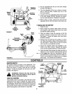
BATTERYCAREAND MAINTENANCE
CHECK FLUID LEVEL
Check fluid level inside each cell of the battery every
two weeks and before and after charging. Always
keep level between the LOWER LEVEL and UPPER
LEVEL lines on battery.