


4. Loosen the hex nut on the scissor mounting
bracket. See figure 13.
5. Start the engine and run at full throttle.
6. Move the hydrostatic control lever until you find
neutral (rear wheels do not rotate in either direc-
tion).
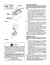
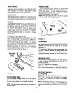
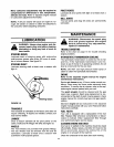
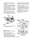
Stabilizer Shaft
Assembly
Disengagement Rod
WARNING: Be careful of the cooling fan
on the hydrostatic transmission.
7. Depress the clutch-brake pedal all the way and
set the parking brake.
8. Shut off the engine.
9. Tighten the hex nut on the scissor mounting
bracket.
10. Thread the speed selector rod in or out of the fer-
rule until the hydrostatic control lever lines up in
the neutral position on the speed control index
bracket.
11. Tighten hex jam nut against the ferrule.
12. Replace the transmission panel and parking
brake knob.
13. Remove the blocks from under the frame and test
the operation of the tractor.
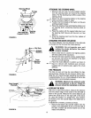
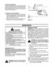
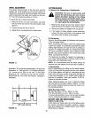
Spring
Stabilizer Plate
Flat Washer
Hairpin Clip
FIGURE 14.
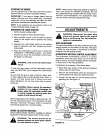
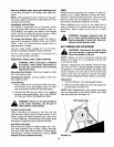
BRAKEADJUSTMENT(See figure15)
The brake is located by the right rear wheel inside the
frame, During normal operation of this machine, the
brakes are subject to wear and will require periodic
examination and adjustment.
WARNING: Do not have the engine run-
ning when you adjust the brake.
To adjust the brake, adjust the nut so the brake starts
to engage when the brake lever is 1/4" to 5/16" away
from the axle housing.
DECKLEVELINGADJUSTMENT
If an uneven cut is obtained, the deck may be leveled
by following instructions in Assembly section.
CUTTING DECKENGAGEMENTADJUSTMENT
The cutting deck engagement may be adjusted to
make certain deck is disengaged when lift lever is in
the disengaged position, or to obtain more drive in the
cutting positions. Correct adjustment as follows.
With the engine off, place the lift lever in the highest
cutting position (first position). Remove the cotter pin
and flat washer which secure the disengagement rod
to the stabilizer shaft assembly. See figure 14.
Shorten the rod by threading it in until the ferrule is
against the back of the slot in the lift shaft assembly,
and the rod lines up with the hole in the stabilizer
shaft. For more belt tension the disengagement rod
must be lengthened. To decrease belt tension the dis-
engagement rod must be shortened.
Check the adjustment by placing the lift lever in the
disengaged position. The deck should move up and
forward, allowing the belt to become loose. Start and
test for disengagement. Repeat procedure as neces-
sary.
Brake
Lever
(_ Disc
ke
I
FIGURE 15.
CARBURETORADJUSTMENTS
&
WARNING: If any adjustments are made
to the engine while the engine is running
(e.g. carburetor), disengage all clutches
and blades. Keep clear of all moving
parts. Be careful of heated surfaces and
muffler.
10