


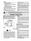
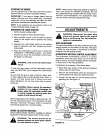
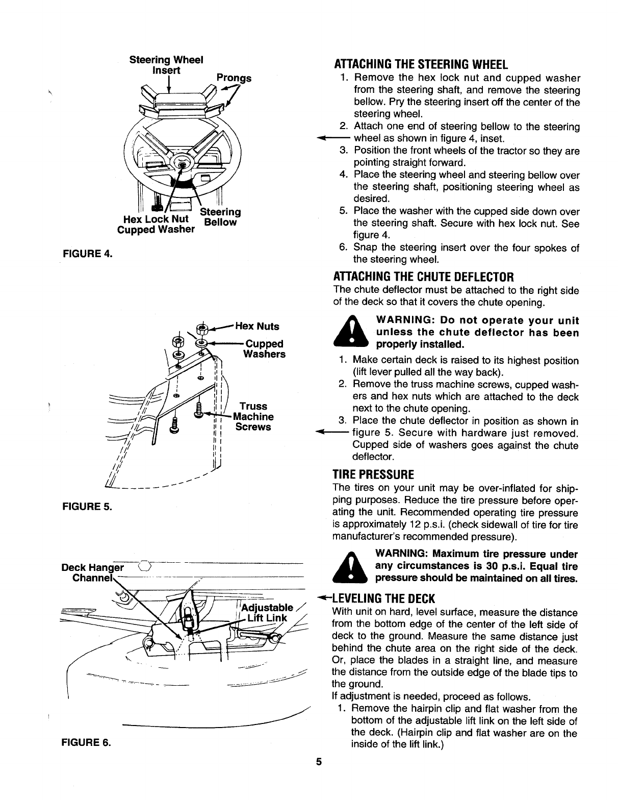
FIGURE4.
SteeringWheel
Insert
Prongs
Steering
HexLockNut Bellow
CuppedWasher
Nuts
Cupped
Washers
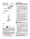
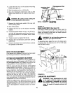
FIGURE5.
DeckHanger -C___-
ustable /
\
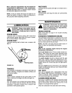
FIGURE 6.
.
3.
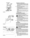
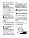
ATTACHINGTHE STEERING WHEEL
1. Remove the hex lock nut and cupped washer
from the steering shaft, and remove the steering
bellow. Pry the steering insert off the center of the
steering wheel.
Attach one end of steering bellow to the steering
wheel as shown in figure 4, inset.
Position the front wheels of the tractor so they are
pointing straight forward.
4. Place the steering wheel and steering bellow over
the steering shaft, positioning steering wheel as
desired.
5. Place the washer with the cupped side down over
the steering shaft. Secure with hex lock nut. See
figure 4.
6. Snap the steering insert over the four spokes of
the steering wheel.
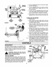
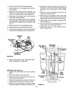
ATTACHINGTHE CHUTEDEFLECTOR
The chute deflector must be attached to the right side
of the deck so that it covers the chute opening.
WARNING: Do not operate your unit
unless the chute deflector has been
properly installed.
.
2.
Make certain deck is raised to its highest position
(lift lever pulled all the way back).
Remove the truss machine screws, cupped wash-
ers and hex nuts which are attached to the deck
next to the chute opening.
Place the chute deflector in position as shown in
figure 5. Secure with hardware just removed.
Cupped side of washers goes against the chute
deflector.
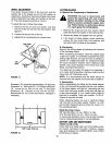
TIRE PRESSURE
The tires on your unit may be over-inflated for ship-
ping purposes. Reduce the tire pressure before oper-
ating the unit. Recommended operating tire pressure
is approximately 12 p.s.i. (check sidewall of tire for tire
manufacturer's recommended pressure).
4_ WARNING: Maximum tire pressure under
any circumstances is 30 p.s.i. Equal tire
pressure should be maintained on all tires.
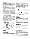
'_-LEVELING THE DECK
With unit on hard, level surface, measure the distance
from the bottom edge of the center of the left side of
deck to the ground. Measure the same distance just
behind the chute area on the right side of the deck.
Or, place the blades in a straight line, and measure
the distance from the outside edge of the blade tips to
the ground.
If adjustment is needed, proceed as follows.
1. Remove the hairpin clip and flat washer from the
bottom of the adjustable lift link on the left side of
the deck. (Hairpin clip and flat washer are on the
inside of the lift link.)
5