


22 www.xilinx.com Virtex-4 LX/SX Prototype Platform
UG078 (v1.2) May 24, 2006
Detailed Description
R
15. PROGRAM Switch
The active-low PROGRAM switch, when pressed, grounds the program pin on the DUT.
16. RESET Switch (Active-Low)
The RESET switch connects to a standard I/O pin on the DUT, allowing the user, after
configuration, to reset the logic within the DUT. When pressed, this switch grounds the
pin.
Table 11 shows the INIT pin locations for the available DUT package types.
17. DONE LED
The DONE LED indicates the status of the DONE pin on the DUT. This LED lights when
DONE is high or if power is applied to the board without a part in the socket.
18. INIT LED
The INIT LED lights during initialization.
19. Platform Flash ISPROM
A 32-Mb Platform Flash In-System Programmable Configuration PROM (ISPROM) is
provided on the board for configuration (see Table 12). Refer to Platform Flash ISPROM
(DS123) at http://direct.xilinx.com/bvdocs/publications/ds123.pdf
for a detailed
description.
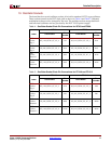
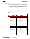
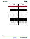
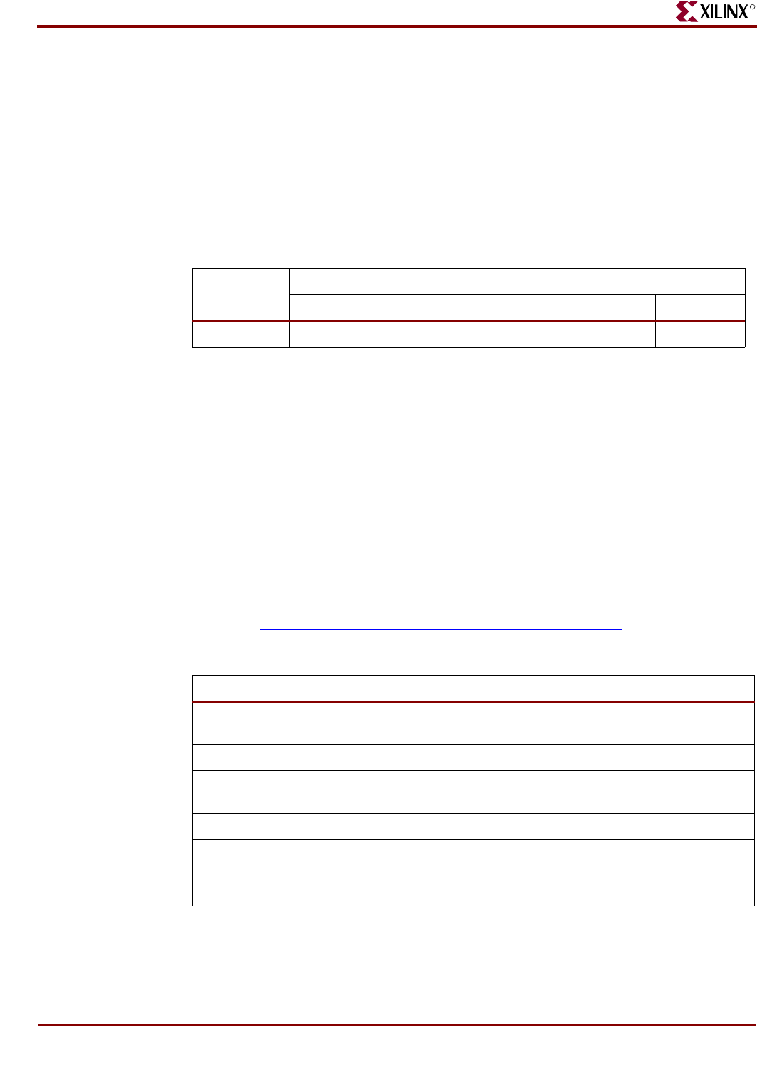
Table 11: User Hardware and Corresponding I/O Pins
Pin Number For Package Type
Label SF363 FF668 FF1148 FF1513
RESET R16 W24 AP21 AH23
Note: Refer to the readme.txt file for implementation of this user pin.
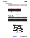
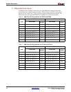
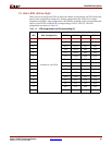
Table 12: Platform Flash ISPROM Configuration
Label Description
J46 Provides power to the ISPROM. These jumpers must be installed for proper
operation of the ISPROM.
J45 Sets the design revision control for the ISPROM.
J43 Enables or disables the ISPROM by placing the address counter in reset and
DATA output lines in high-impedance state.
J42 Sets the ISPROM for serial or select map configuration.
J8 Selects one of two modes of CCLK operation:
• ISPROM provides CCLK (PROM CLKOUT)
• FPGA provides CCLK (FPGA CCLK)