


16 www.xilinx.com Virtex-4 LX/SX Prototype Platform
UG078 (v1.2) May 24, 2006
Detailed Description
R
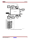
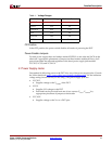
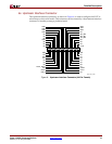
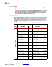
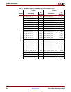
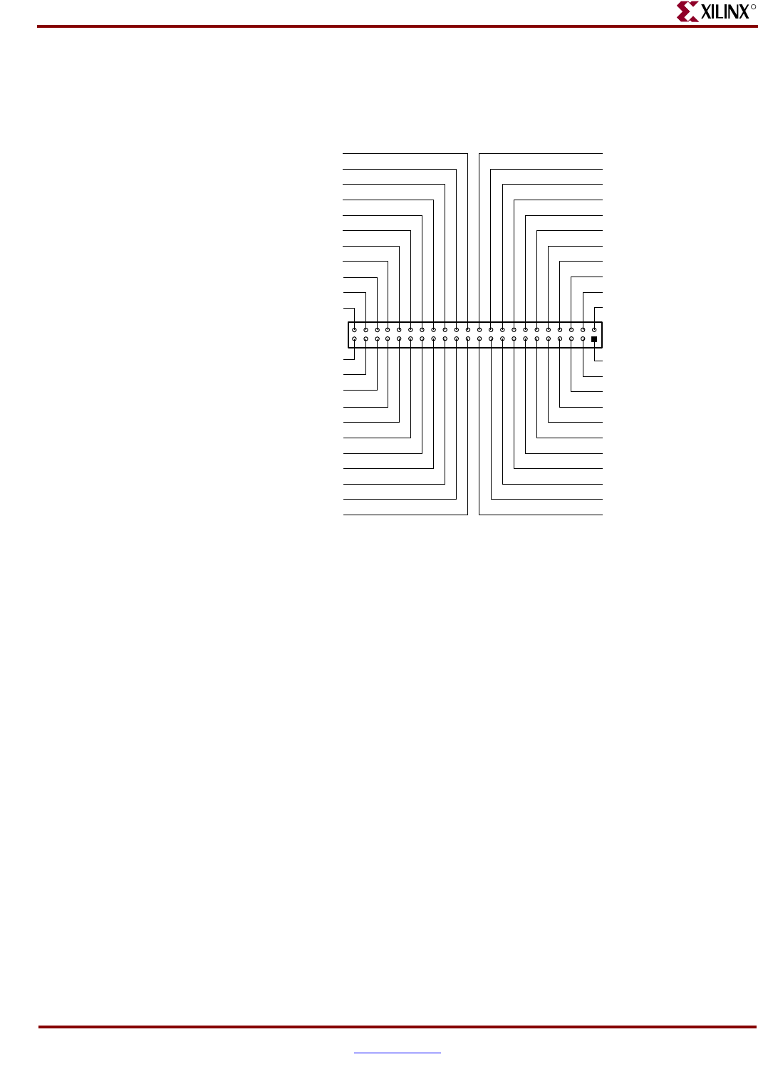
6d. Downstream Interface Connector
The downstream interface connector, as shown in Figure 7, passes serial configuration
information to the DUT in the downstream prototype platform board.
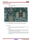
7. Prototyping Area
The prototyping area accommodates 0.10-inch spaced ICs. The kit contains headers that
can be soldered to the breakout area, if desired. Power and ground buses are located at the
top and bottom edges, respectively, of the prototyping area.
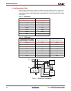
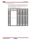
8. VCCO-Enable Supply Jumpers
Virtex-4 series devices have 9 to 17 SelectIO banks, labeled 0 through 16, each with a
VCCO-enable supply jumper. The VCCO-enable supply jumpers can connect each bank to
one of the two onboard supplies, VCCINT or the VCCO supply. These jumpers must be
installed for the Virtex-4 device to function normally.
9. VBATT
An onboard battery holder is connected to the VBATT pin of the DUT. If an external power
supply is used, the associated jumper must be removed and instead use a 12 mm lithium
coin battery (3V).
Figure 7: Downstream Interface Connector (44-Pin Male)
UG027_07_051004
NC
NC
NC
NC
NC
NC
NC
NC
NC
NC
NC
NC
NC
NC
NC
NC
DOUT_BUSY
NC
NC
CLK
DONE
NC
NC
NC
NC
INIT
PROG
NC
TCK
NC
NC
TMS
DOWNSTREAM_TDI
TDO
GND
GND
GND
GND
GND
GND
GND
NC
NC
GND
A1
A2
A3
A4
A5
A6
A7
A8
A9
A10
A11
A12
A13
A14
A15
A16
A17
A18
A19
A20
A21
A22
B1
B2
B3
B4
B5
B6
B7
B8
B9
B10
B11
B12
B13
B14
B15
B16
B17
B18
B19
B20
B21
B22