


10 www.xilinx.com Virtex-4 LX/SX Prototype Platform
UG078 (v1.2) May 24, 2006
Detailed Description
R
Detailed Description
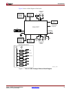
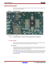
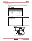
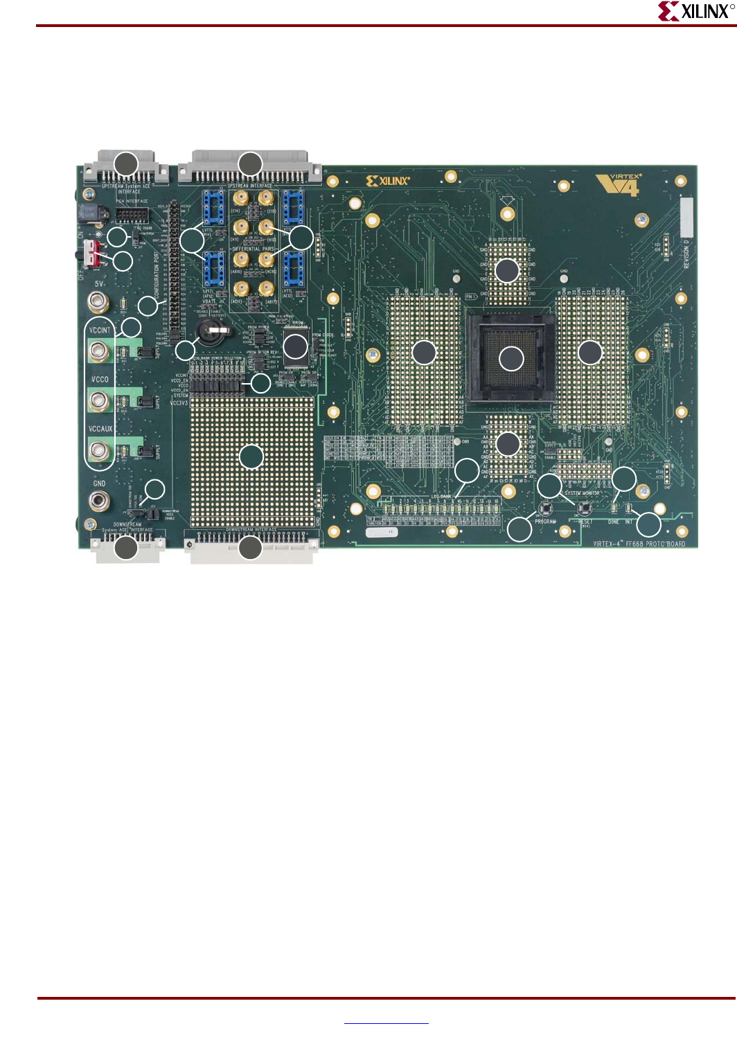
The Virtex-4 prototype platform board is shown in Figure 2. Each feature is detailed in the
numbered sections that follow.
1. Power Switch
The board has an onboard power supply and an ON|OFF power switch. When lit, a green
LED indicates power from the power brick connector or the 5V jack.
On Position
In the ON position, the power switch enables delivery of all power to the board by way of
voltage regulators situated on the backside of the board. These regulators feed off a 5V
external power brick or the 5V power supply jack.
The voltage regulators deliver fixed voltages. Maximum current range for each supply will
vary. Table 1, page 9 shows the maximum voltage and maximum current for each onboard
power supply. If the current exceeds maximum ratings, use the power jacks to supply
power to the DUT.
Figure 2: Detailed Description of Virtex-4 LX/SX Prototype Platform Components
UG078_02_101904
19
1
2
4
3
5
9
8
6a 6c
6b 6d
10
11
15
16
14
17
18
7
12
13
13
1313