


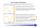

Frequency Generator for the Spartan-3E Starter Kit 9
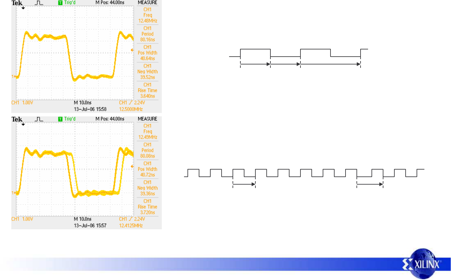
Phase Accumulator Waveforms
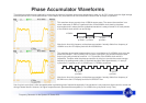
The following waveforms were obtained by monitoring the output of the phase accumulator presented on stake pin ‘J4-IO9’. In each case the digital storage
oscilloscope was set to infinite persistence in order capture any fluctuations over time and therefore observe the ‘envelope’ of operation.
This waveform shows a pretty clean 12.5MHz square wave. The reason the waveform is so
clean is because 12.5MHz is a perfect division of the 200MHz clock used by the phase
accumulator and it means that the synthesized waveform is always formed of 16 clock periods
of the 200mHz clock with 8 Low and 8 High.
Note that to force this frequency at the phase accumulator I actually dialled in a frequency of
100MHz on to the LCD display such that N=10000000 hex.
12.5MHz
8 cycles
@ 200MHz
8 cycles
@ 200MHz
This waveform shows what happens when you try to synthesize a 12.4125MHz clock using the
phase accumulator. There is clearly 5ns of cycle to cycle jitter in this situation because each
output cycle really should be formed of ~16.113 periods of the 200MHz clock which is
impossible. Therefore what the phase accumulator is doing is to provide the correct average
frequency by making some cycles of 16 periods and then make approximately 1 in every 9
cycles have 17 periods; a mix of 12.5MHz and 11.767MHz waveforms.
Note that to force this frequency at the phase accumulator I actually dialled in a frequency of
99.3MHz on to the LCD display such that N=0FE353F7 hex
16 cycles
@ 200MHz
17 cycles
@ 200MHz
16 cycles
@ 200MHz
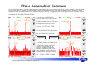
5ns of cycle to cycle jitter is often acceptable when synthesizing lower frequencies especially if the waveform is only used as a digital clock for control and
timing of slower events. However, for higher frequencies such jitter becomes acceptable (i.e. at 100MHz the cycle period is only 10ns).