


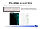
Frequency Generator for the Spartan-3E Starter Kit 8
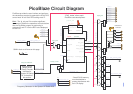
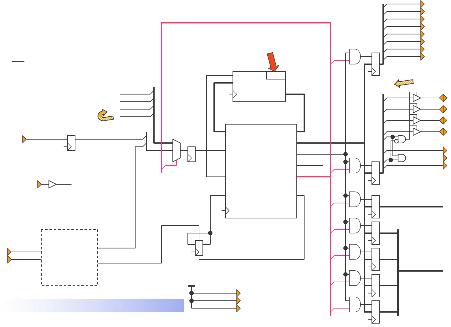
PicoBlaze Circuit Diagram
strataflash_oe
strataflash_ce
strataflash_we
Vcc
*
*
*
*
StrataFLASH memory
must be disabled to
prevent interference with
the LCD display.
interrupt_control
‘JTAG_loader’ allows rapid
PicoBlaze code development.
port_id
kcpsm3
processor
instruction
write_strobe
clk
out_port
read_strobe
address
reset
interrupt_ackinterrupt
in_port
instruction
address
fg_ctrl
program_rom
instruction
address
clk
port_id
write_strobe
out_port
read_strobe
interrupt_ack
interrupt
in_port
JTAG
proc_reset
clk
kcpsm3_reset
0
input_ports
led(6)
7
led(5)
led(4)
led(3)
led(2)
led(1)
led(0)
led(7)
output_ports
rotary_a
rotary_press
rotary_b
lcd_rs
lcd_e
lcd_rw
lcd(7)
6
lcd(6)
lcd(5)
lcd(4)
lcd(7)
lcd(6)
lcd(5)
lcd(4)
bidirectional
LCD data
rotary_press_in
See reference
design called
‘Rotary Encoder
Interface for
Spartan-3E Starter
Kit’ for details of
this section.
rotary_event
rotary_left
rotary_filter & direction
clk
50MHz clock to all items on this page
2
3
4
5
1
dds_scaling_word
dds_control_word
[7:0]
[15:8]
[23:16]
[31:24]
[4:0]
PicoBlaze provides the user interface and performs
the calculations required to generate the 32-bit DDS
control word ‘N’ and 5-bit DDS scaling word ‘D’.
Hint
– The ‘fg_ctrl.psm’ file contains significant
comments to explain the operations and calculations
that the PicoBlaze program is performing to
generate ‘N’ and ‘D’ from the BCD value displayed
on the LCD.
N
D