


Frequency Generator for the Spartan-3E Starter Kit 14
Exercises, Experiments and Suggestions
Here are some exercises, experiments and suggestions for you to consider based on this reference design. Although several are specific to the Spartan-
3E Starter Kit, most are portable to your own boards and designs where I hope you will find the design concept useful.
How fast is yours?
The PicoBlaze controller does not limit the upper frequency that you can enter to see how high the frequency is that your board can generate.
Hint 1 – Although the display supports up to 999MHz, the largest valid value you can enter is 212.499999MHz because this sets N=0FFFFFEA.
Hint 2 – The output from the second DCM is always divided by at least 2 before it reaches the output pin, so internally a clock can be faster.
Hint 3 – As you increase the frequency you will reach the limit of I/O performance. Experiment with increasing output drive strengths and FAST slew rates.
Save Oscillators and Save $
This reference design could be the way to save money by replacing a set of different crystal oscillators required to support multiple standards etc. This
design together with the board allows you to directly try the output with your own products and see if it works for you. The plots shown in this document
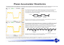
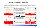
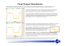
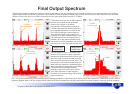
clearly show that the final output has very low cycle to cycle jitter compared with the output from a phase accumulator DDS circuit. However, it is also
shown that the output still has some additional frequency components as it tracks the average frequency. In some applications this will have no effect
whilst others may find it an issue. Some applications can actually benefit from the partial spread spectrum effect (i.e. reduced EMC).
Fixed Frequency Modules
If you know which frequencies you require, then reduce the design to a phase accumulator driven by a constant ‘N’, the DCMs and a fixed counter divider
(no multiplexer).
Hint – If you still operate the phase accumulator at 200MHz, then use the supplied design on the board to calculate your ‘N’ and ‘D’ values for you.
Hint – Remember to share the 200MHz fast clock between several phase accumulators to save DCMs.
Accurate Measurements
If you have access to superior measurement equipment, then measure the frequency generator output for yourself and observe the tracking nature of the
output. Be careful not to confuse I/O and PCB effects with what you are attempting to measure using such good equipment.
Design Throttling
This term is given to the concept of changing the frequency depending on the demands of an application over time. This is a way to save power since
power consumption is directly proportional to operating frequency. The frequency aligned mode allows you to switch between frequencies without causing
glitches and you can prove this with the design provided.
Hint – Increasing ‘CCount’ (read notes in ‘frequency_generator.vhd’) will provide very smooth but relatively slow rates of change in frequency.
Simple Frequency Measurements using the Spartan-3E Starter Kit
Create a fixed frequency version of the design for a frequency of your choice. Then insert that module into the reference design called ‘PicoBlaze
Frequency Counter for the Spartan-3E Starter Kit Board’ in place of one of the existing sources so that you can observe the output frequency.
Hint – The output frequency should be correct, but you should be observing a variation above and below as the DCM tracks the average frequency value.
Turn it off!
Probably the best way to convince yourself that the frequency aligned mode of the DCM is really doing something special is to turn it off (remove the
special BITGEN option) and then look at the output waveform on an oscilloscope particularly at frequencies >50MHz.