


Frequency Generator for the Spartan-3E Starter Kit 11
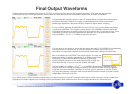
Final Output Waveforms
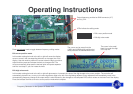
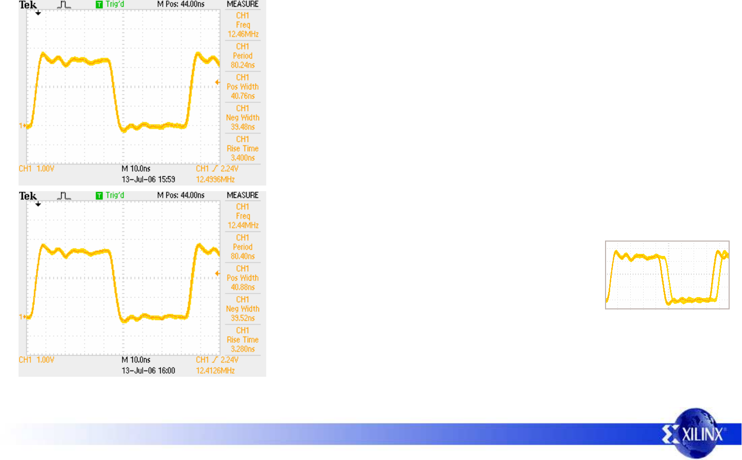
These waveforms were obtained from stake pin ‘J4-IO12’ and reflect the final output of the frequency generator. Once again the digital storage
oscilloscope was set to infinite persistence in order capture any fluctuations over time and therefore observe the ‘envelope’ of operation.
In these cases the frequency shown on the LCD display directly corresponds to the frequency
provided at the output. However it is useful to understand what the phase accumulator is
generating to appreciate if the second DCM in ‘frequency aligned mode’ is helping.
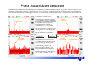
For this 12.5MHz waveform N=08000000 hex and D=02 hex. So in fact the phase accumulator
is synthesizing 6.25MHz. This is again a perfect division of the 200MHz clock and means that
the synthesized waveform is always formed of 32 clock periods with 16 Low and 16 High. There
is therefore no obvious cycle jitter introduced and therefore it is not surprising that the final
output (6.25MHz × 16 / 2
(2+1)
= 12.5MHz) is also nice and clean.
Hint – When using a DCM in frequency aligned mode, you must accept that it does NOT maintain phase lock as it does in all other ‘normal’ modes. More
significantly the output frequency is the average of the input frequency which means there will often be a slight difference as it tracks the input.
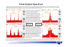
You may have to look closely to notice that this second plot really is 12.4125MHz. It is immediately
clear that there is no obvious cycle to cycle jitter present. To confirm that this isn’t just a
coincidence, we must again consider what the phase accumulator is doing at the same time.
The final output (12.1425MHz × 16 / 2
(3+1)
= 12.1245MHz) shows that the frequency aligned
mode of the DCM is tracking the average frequency of the input waveform and totally ignoring
the phase of the input waveform resulting in a very low cycle to cycle jitter. In fact the DCM is
only using the frequency information from the input waveform and the output cycle jitter is totally
independent of the input cycle jitter.
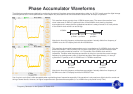
With 12.4125MHz set, N=0FE353F7 hex and D=03 hex. So in fact the
phase accumulator is actually synthesizing 12.4125MHz as well. More
significantly, it means that the phase accumulator is generating
exactly the same waveform as we observed previously on page 9 in
which there was 5ns of cycle to cycle jitter present (see right).
Phase Accumulator