


Installation
975-0053-01-01 2–21
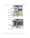
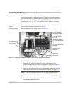
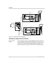
Connecting Inverters in Parallel
Reasons and
requirements
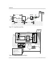
Sun Tie XR inverters may be connected in a parallel configuration to
harvest additional energy from the sun. In this configuration, a separate
solar array is required for each Sun Tie XR unit. The output of each Sun
Tie XR feeds a dual-pole 15-amp circuit breaker (L1 and L2) in the main
utility breaker panel.
Connecting AC and
DC wiring
The procedure for wiring the additional Sun Tie XR is exactly the same as
previously described for the AC and DC wiring. Additional Sun Tie XR
inverters can be added in the future as required.
An example of a parallel configuration is shown in Figure 2-16.
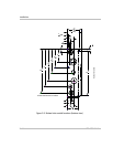
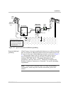
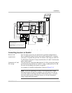
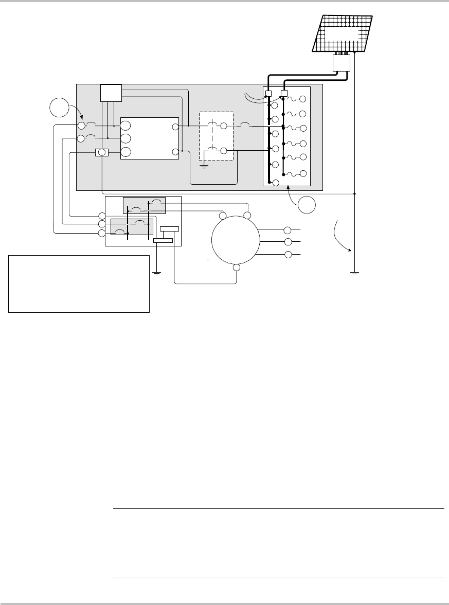
Figure 2-15 Simplified electrical wiring diagram (using PV bypass terminals)
INVERTER
+
–
EXTERNAL
COMBINER BOARD
+
–
L1
L2
G
PV GROUND FAULT
BREAKERS (OPTION)
100 A
1 A
UTILITY
GRID
A
SOV
NOTES:
INSTALLER CONNECTIONS REQUIRED AT POINTS
(A)
AND
(B)
TO
THE INVERTER ENCLOSURE.
THE UTILITY METER MAY BE A BI-DIRECTIONAL METER OR DUAL
METERS MAY BE USED.
OBTAIN UTILITY COMPANY APPROVAL BEFORE INSTALLING.
975-S00-003A
15 A
15 A
LIGHTNING
ARRESTOR
(OPTION)
100 A
20 A
+
20 A
+
20 A
+
20 A
+
20 A
+
20 A
+
–
–
–
–
–
–
B
STXR UNIT
L2
MAIN SERVICE PANEL
L1
GROUND
G
L1
L2
N
UTILITY METER
L2
L1
Main
Breakers
Sun-Tie
Breakers
Extra Ground Rod
Only Required on
Long Runs > 100
feet (30 m).
NEUTRAL
L2
L1
G
PV ARRAY
PV COMBINER BOARD
–
+
–
+
BYPASS TERMINALS
N
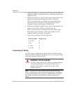
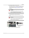
Note:
If you are combining two Sun Tie XR inverters into a single
dual-pole breaker (30 amp, for example), you will need to size the AC
wires and conduit to the larger breaker. If this breaker trips, it will also
shut down both inverters. For these reasons, we do not recommend
using a single dual-pole breaker.