


Installation Planning
975-0053-01-01 2–5
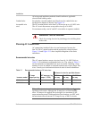
AC circuit breaker requirements
The main service panel must dedicate a 15 amp minimum, double pole
breaker (120/240 volts AC) to operate the Sun Tie XR.
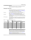
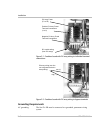
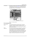
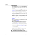
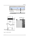
Planning DC Connections
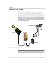
DC connections include all the wires and connectors between your PV
array and the Sun Tie XR’s combiner board. Figure 2-1 and Figure 2-2
show the combiner board and connection points. Figure 2-14 and Figure
2-15 show simplified diagrams of the entire installation.
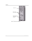
Wire Sizes The DC connections are made on the combiner board inside the
Sun Tie XR. The combiner board accepts wire sizes from #6–14 AWG.
Refer to Table 2-2 for minimum recommended wire sizes.
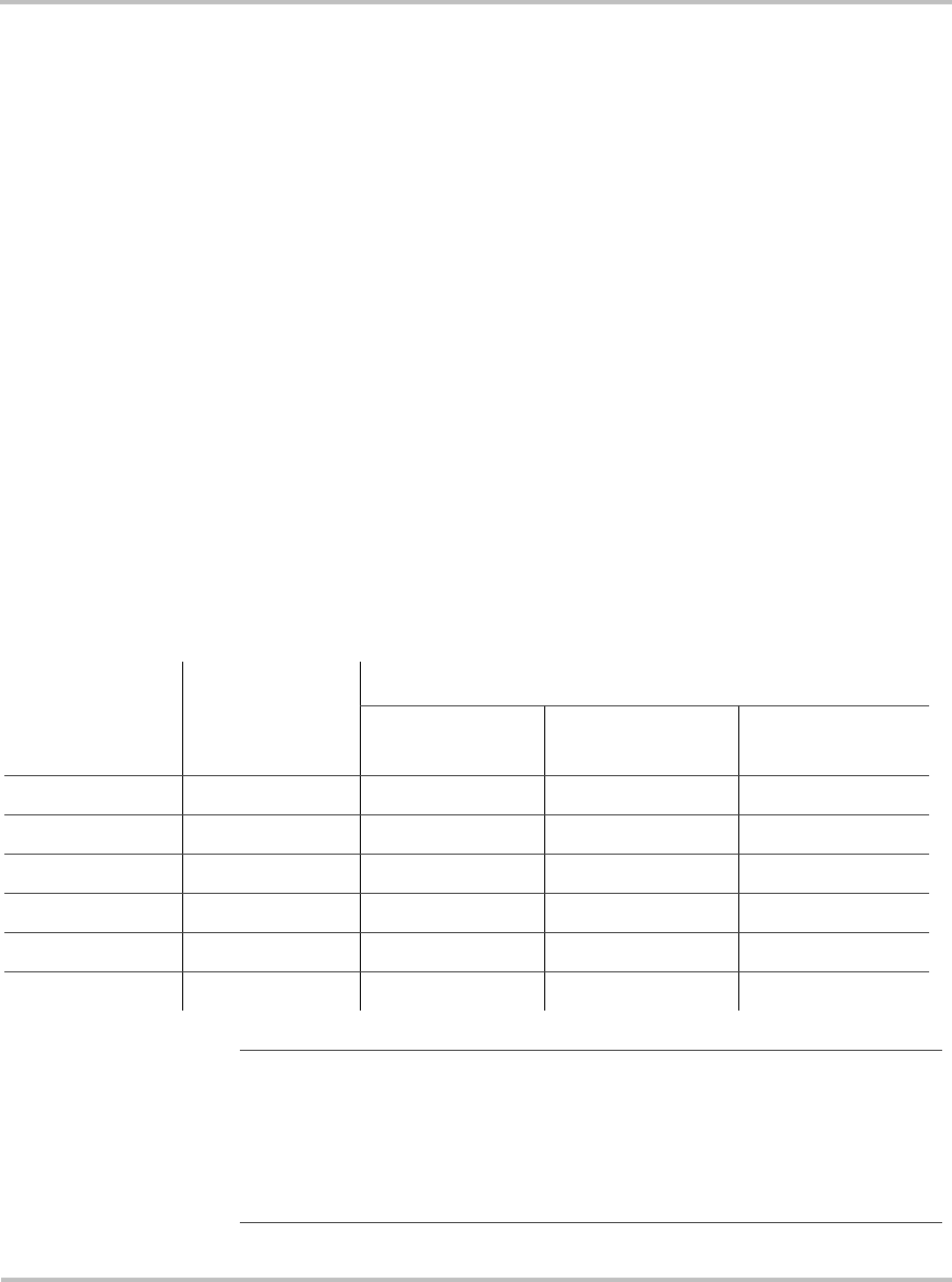
Exceptions The values in Table 2-2 are the minimum recommended wire sizes.
Installing a large number of wires in conduit or enclosed locations may
require larger wire sizes. Consult your local or national electrical code for
more information.
NEC Restrictions The National Electrical Code (NEC) places restrictions on minimum DC
wire bending radius. A #6 AWG wire is the largest that may be used on
the Sun Tie XR when connecting to the individual fused circuits of the
combiner board.
Table 2-2 Recommended minimum DC wire sizes
DC amps (I
mp
)
(from PV array)
NEC amps
(amps x 156%)
Minimum wire size for specified distance
0–25 ft
one way
25–50 ft
one way
50–100 ft
one way
1.0 1.6 14 AWG 14 AWG 14 AWG
3.0 4.7 14 AWG 12 AWG 10 AWG
5.0 7.8 12 AWG 10 AWG 6 AWG
7.0 10.9 12 AWG 8 AWG 6 AWG
9.0 14.0 10 AWG 8 AWG Not Recommended
11.0 17.2 10 AWG 6 AWG Not Recommended
Note:
For an installation requiring a two-wire run (positive and
negative), the PV array wires can bypass the individual fused combiner
board terminals and connect directly to the input terminals (through an
externally mounted DC fused combiner box) by using the positive and
negative bypass terminals on the combiner board. Refer to Figure 2-2
and Table 2-2 for connection and wire sizes.