


Installation
2–4 975-0053-01-01
All wiring and installation methods should conform to applicable
electrical and building codes.
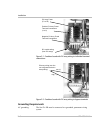
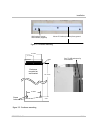
Conduit holes Pre-plan the wire and conduit runs. Knockouts for conduit holes are
located on the bottom of the unit. See Figure 2-9.
Acceptable wire
sizes
The DC terminal blocks in the Sun Tie XR accept up to a #6 AWG wire.
The AC circuit disconnects accept cable sizes up to #6 AWG.
For maximum safety, run AC and DC wires/cables in separate conduits.
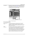
Planning AC Connections
AC connections include all the wires and connectors between the
Sun Tie XR AC output breakers and the main utility electrical panel.
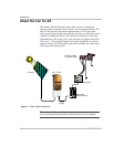
Figure 2-14 and Figure 2-15 show simplified diagrams of the entire
installation.
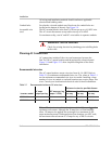
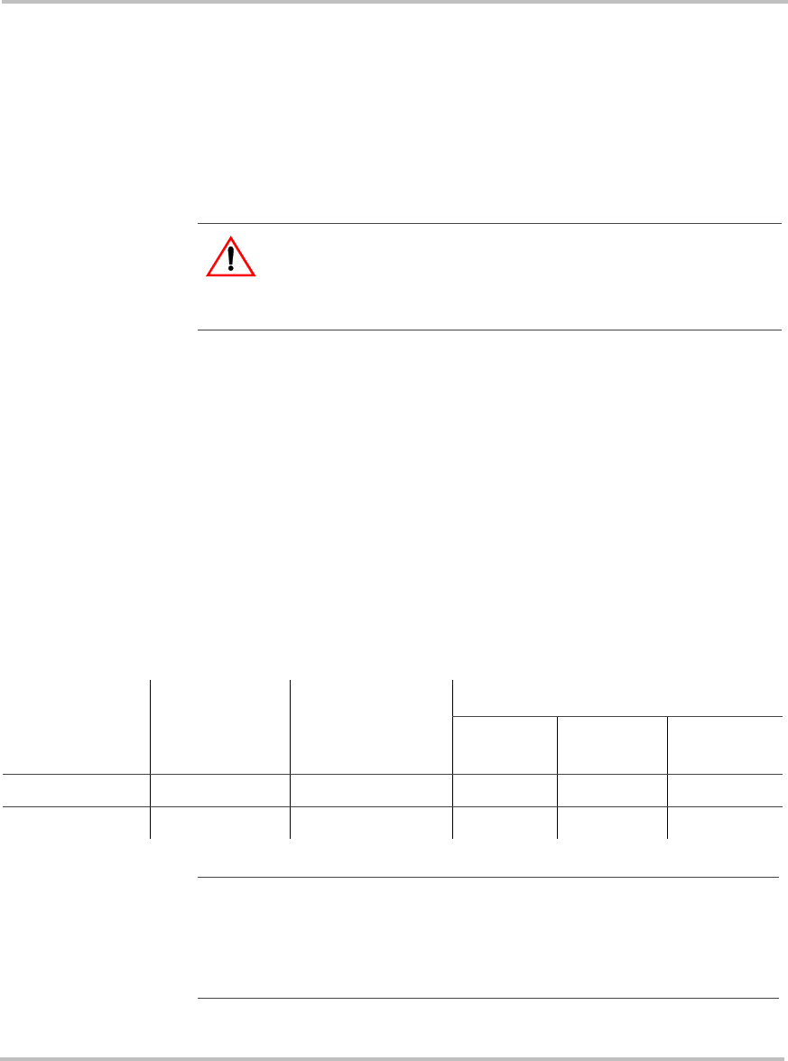
Recommended wire sizes
The AC output breakers accept wire sizes from #6–14 AWG. Refer to
Table 2-1 for minimum recommended wire size. The values in Table 2-1
are the minimum recommended wire sizes in conduit. Installing a large
number of wires in conduit or enclosed locations may require larger wire
sizes. Consult your local/national electrical code for more information.
WARNING: SHOCK HAZARD
Check for existing electrical or plumbing prior to drilling holes
in the walls.
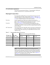
Table 2-1 Recommended minimum AC wire sizes
Inverter model
AC amps
output per leg
NEC amps per leg
(amps x 125%)
Minimum wire size for specified distance
0–50 ft
one way
50–100 ft
one way
100–200 ft
one way
STXR1500 6.3 7.9 14 AWG 10 AWG 8 AWG
STXR2500 10.4 13.0 12 AWG 8 AWG 6 AWG
Note:
The six-circuit combiner board is rated for 100 amps (I
mp
) of
maximum real current. Although the 20 amp fuses will theoretically
allow 120 amps to be applied, always design for a maximum of 100
amps maximum current. With appropriate fuse deratings, per NEC code,
the maximum allowed current is 16 amps for any of the six circuits.