28 Assembly
15916 (Rev. 3/30/2007)
ASSEMBLY
DEALER SET-UP INSTRUCTIONS
These instructions are for the assembly of the MD80
and D80. Many of the procedures apply to both units.
When an instruction applies to a specific unit, the sec-
tion heading will indicate which unit.
Assembly of this cutter is the responsibility of the
WOODS dealer. It should be delivered to the owner
completely assembled, lubricated and adjusted for nor-
mal cutting conditions. Complete check lists when
assembly is complete.
The cutter is shipped partially assembled. Assembly
will be easier if components are aligned and loosely
assembled before tightening hardware. Recommended
torque values for hardware are located on page 58.
Select a suitable working area. Open parts boxes and
lay out parts and hardware to make location easy.
Refer to illustrations, accompanying text, parts lists and
exploded view drawings.
Make sure spring-activated locking pin or collar
slides freely and is seated firmly in tractor PTO
spline groove.
Always wear relatively tight and belted clothing
to avoid getting caught in moving parts. Wear
sturdy, rough-soled work shoes and protective
equipment for eyes, hair, hands, hearing, and head;
and respirator or filter mask where appropriate.
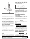
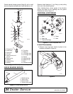
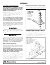
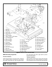
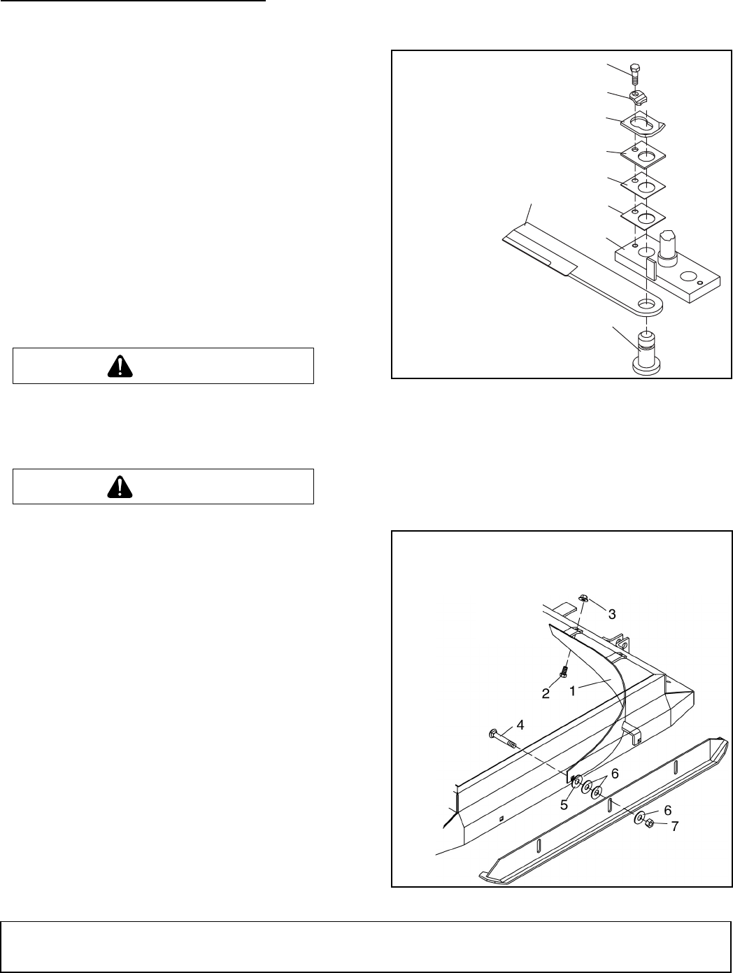
Blade Installation (Figure 20)
Either place cutter on stands or hang to permit access
to both top and bottom. Make sure cutter is secured to
prevent it from falling.
Liberally coat blade pin and crossbar hole with Never-
Seez® or equivalent. Make sure blade is offset away
from deck and cutting edge is positioned for counter-
clockwise rotation as viewed from top of deck.
Install blade pin (9) up through blade (8) then through
hole in crossbar and push firmly against crossbar (7).
Install as many spacers (4, 5 or 6) as possible and still
be able to slide keyhole plate (3), with ears up as
shown, into blade pin groove. Place blade pin clip (2)
over keyhole plate and into blade pin groove. Secure
with bolt (1). Repeat for opposite blade.
Blade should be snug but swivel on pin without exces-
sive force. Retain any spacers not used in installation
for use when blade wears or on future installations.
Figure 20. Blade Installation
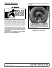
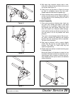
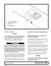
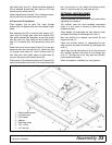
Distribution Baffle Installation (Figure 21)
A distribution baffle is supplied. It is recommended
when mowing grass and weeds. It should not be used
when operating cutter in heavy brush. Remove the two
rear carriage bolts from the left side skid. Place baffle
(1) under cutter frame and attach as shown.
Figure 21. Distribution Baffle Installation
WARNING
CAUTION
CAUTION
9
8
7
6
5
4
3
2
1
CD3818
1. Bolt
2. Blade pin clip
3. Keyhole plate
4. Spacer
5. 18 GA Spacer
6. 20 GA Spacer
7. Crossbar
8. Blade
9. Blade pin
1. Distribution baffle
2. 1/2 x 1" Bolt
3. 1/2" Flanged hex lock nut
4. 5/8 x 2" Carriage bolt
5. 3/4" Flat washer
6. 5/8" Flat washer
7. 5/8" Nut


