Owner Service 19
15916 (Rev. 3/30/2007)
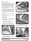
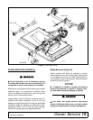
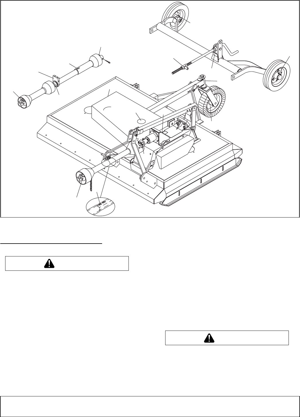
Figure 7. Lubrication Points
BLADE SERVICING (FIGURE 8)
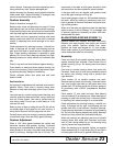
On pull-type units, a pin is installed to prevent
the height adjustment crank from detaching. Do
not operate or service unit unless pin is installed.
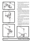
Blocking the cutter before working underneath provides
additional safety. If a mechanical or hydraulic failure
occurs, the blocks will support the cutter and prevent
anyone under it from being crushed.
Inspect blades, each time before operating cutter, for
condition and proper installation. Check to be sure
blades are snug but still swivel on blade pin (see Blade
Installation, page 20). Replace any blade that is bent,
excessively nicked, worn or has any other damage.
Small nicks can be ground out when sharpening.
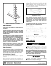
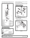
Blade Removal (Figure 8)
Rotate crossbar until blade pin assembly is directly
below access hole in rear of cutter frame. Remove bolt
(1) and blade pin lock clip (2). Slide keyhole plate (3)
out of blade pin groove and remove. Remove spacers
and drive pin out of crossbar.
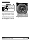
NOTICE
■ If blade pin is seized in crossbar and extreme
force will be required to remove it, support cross-
bar from below to prevent damage to spindle.
Your dealer can supply genuine replacement
blades. Substitute blades may not meet original
equipment specifications and may be dangerous.
MOUNTED
PULL-TYPE
6
9
8
7
5
4
3
2
1
14
1
13
12
10
11
CD3847
7
9
PULL-TYPE
WARNING
CAUTION
CAUTION


