


34 Assembly
MAN0450 (10/28/2005)
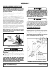
PUMP MOUNTING BRACKET INSTALLA-
TION
The only time the backhoe may be operated
from a position other than the operator seat is dur-
ing backhoe attachment and removal. Operator
must:
• Read Mounting Kit Manual instructions on
attaching and removing backhoe and use
extreme care.
• Always stand between rear tire and backhoe
stabilizer arms or along side of tractor to avoid
being trapped should the boom swing control
be accidentally activated.
Make sure spring-activated locking pin or collar
slides freely and is seated firmly in tractor PTO
spline groove.
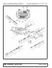
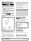
Figure 23. Pump Mounting Bracket Installation
If you are using a sub-frame mounting, refer to the
pump mounting instructions provided with the sub-
frame.
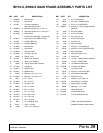
The pump mounting bracket is designed to slip over
tractor drawbar. The best installation is to place bracket
offset toward tractor and pump offset down; however,
offset may be reversed if interference occurs, Figure
23.
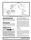
On tractors with non-standard drawbars, it may be nec-
essary to modify pump bracket by enlarging the open-
ing. Bracket may also be inverted and retained on the
top link bar. Whatever mounting is used, it is important
that pump be restrained from rotating.
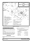
Attach pump mounting plate (18) to pump with bolts
(19) and nuts (20), Figure 22.
Check all hydraulic fittings and lines to be sure they are
tight and free of kinks and twists.
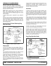
SEAT INSTALLATION AND ADJUSTMENT
The seat may be adjusted fore, aft, up and down for
operator comfort. It is necessary to use the two adjust-
ments together. Moving the seat down also moves it
forward, moving it up also moves it rearward. The fore
and aft adjustment may be used with the up and down
adjustment to obtain desired position. Never operate
the backhoe unless manufacturer's 3-point hitch Saf-T-
Lok Limiter or sub-frame has been installed, adjusted
and operator's area (shown in decal 1011992, see
decal page 11) is free from obstructions.
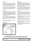
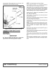
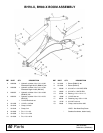
INSTALL OPTIONAL STABILIZER
STREET PAD
1. Attach two rubber stabilizer pads (7) to the bottom
stabilizer pad (2) using three lock nuts (6).
2. Repeat step for opposite side stabilizer.
Figure 24. Stabilizer Pad Installation
OPTIONAL EQUIPMENT
1012552 3-Point Mount Kit
See 3-Point Mount Kit manual for installation instruc-
tions.
1015090 Mechanical Thumb (BH70-X)
1015100 Mechanical Thumb (BH80-X)
See Mechanical Thumb manual for Installation instruc-
tions.
1. Pump
2. Pump mounting
bracket
A. Pump mounting
bracket modification