


Assembly 31
MAN0450 (10/28/2005)
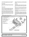
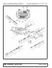
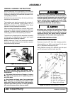
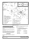
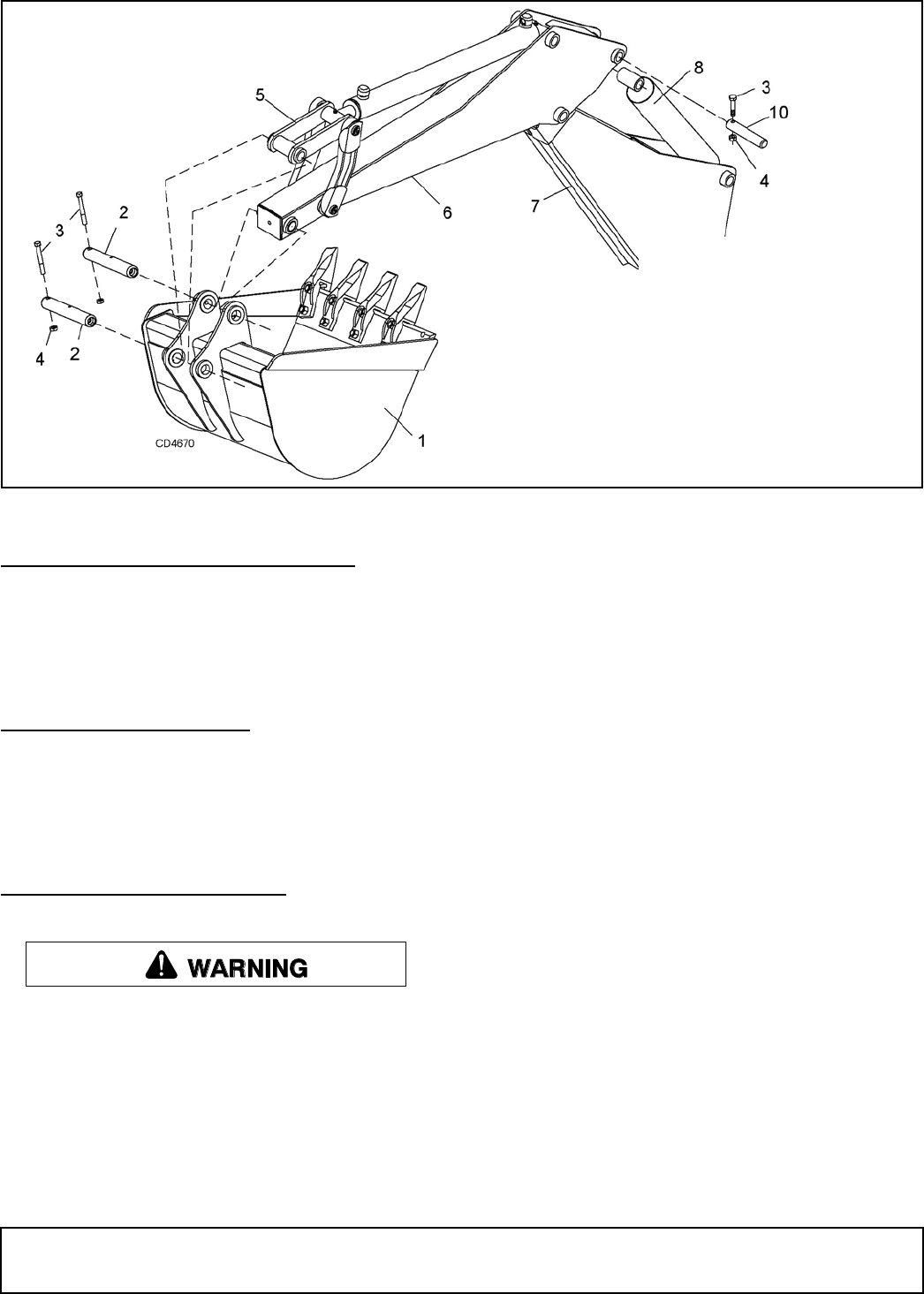
Figure 20. Dipper and Bucket Installation (Typical Assembly)
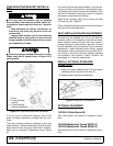
DIPPER CYLINDER INSTALLATION
Remove pivot pin (10) from end of dipper (6). Attach
dipper cylinder (8) to dipper (6) with pivot pin and
secure with bolt (3) and lock nut (4). Make sure hydrau-
lic hoses are not twisted after boom and dipper are
assembled.
BUCKET INSTALLATION
9", 12", 16", 18" and 24" buckets are available with this
backhoe. Remove pivot pins (2) from end of bucket link
(5) and dipper (6). Attach bucket (1) to bucket link and
dipper with pivot pins (2) and secure with bolts (3) and
lock nuts (4).
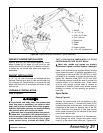
HYDRAULIC INSTALLATION
Refer to Figure 21.
Keep hands and body away from pressurized
lines. Use paper or cardboard, not hands or other
body parts to check for leaks. Wear safety goggles.
Hydraulic fluid under pressure can easily penetrate
skin and will cause serious injury or death.
Make sure that all operating and service person-
nel know that if hydraulic fluid penetrates skin, it
must be surgically removed as soon as possible by
a doctor familiar with this form of injury or gan-
grene, serious injury, or death will result. CON-
TACT A PHYSICIAN IMMEDIATELY IF FLUID
ENTERS SKIN OR EYES. DO NOT DELAY.
Make sure shields and guards are properly
installed and in good condition. Replace if damaged.
Power to the backhoe can be supplied directly from the
tractor hydraulic system. A hydraulic requirement of 5-
7 gallons per minute and 2000 PSI (BH70-X) or 2400
psi (BH80-X) is necessary to operate the backhoe effi-
ciently. 3/8" diameter hoses (SAE 100 R1 with 2500
PSI working pressure) should be used to connect the
hydraulic source to the backhoe valve. These hoses
must be long enough to allow ease of removal or
attachment of backhoe. Hoses must include external
shielding to prevent oil from spraying on operator if
hose fails.
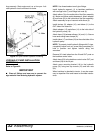
Open-Center
Refer to Figure 21.
Remove the console cover from the backhoe to gain
access to control valve (1). Connect 3/8" hoses (2 & 3)
to the backhoe inlet and outlet ports. Install couplers (4)
compatible to the tractor on opposite end of the 3/8"
hoses. Determine the direction of flow and connect
tractor pressure hose (6) to the inlet side of the control
valve (under left foot rest).
Note: The backhoe will not function if oil is routed back-
wards through the valve. Connect the tractor return
hose (5) to the control valve outlet port. Tighten all fit-
1. Bucket
2. 1 x 7.12" Pin
3. 5/16 x 2-1/2" Bolt
4. 5/16" Lock nut
5. Bucket link
6. Dipper
7. Boom
8. Dipper cylinder
10. 1.12 x 5.5" Headless pin