


Dealer Service 25
MAN0450 (10/28/2005)
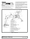
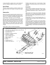
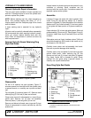
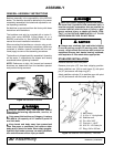
ADJUST CONTROL VALVE LINKAGE
Reconnect control linkage to valve.
Control handles should be positioned as shown.
When completing a maintenance function on the valve,
perform a functional test by placing control handles in
their various positions and make certain the correct
operation occurs corresponding to the decals on the
operator's console. Pay specific attention to the float
position of the boom. Do not operate backhoe if func-
tions differ from the decal.
If the functions differ from the decal, check to make
sure control linkage is correctly installed and check
plumbing schematics to make sure hoses are correctly
connected.
Figure 14. Control Lever Adjustment
BH80-X
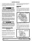
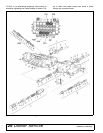
HYDRAULIC VALVE REPAIR
Refer to Figure 15.
Valve repair should be accomplished in a clean work
place. Individual components for many of the assem-
blies are not available as repair parts. This will simplify
repair and allow you to replace complete assemblies.
Pressure Settings on Port Relief Valves
Pressure settings on port relief valves are pre-set at
the factory. Although they are adjustable, they must not
be reset in the field using backhoe hydraulic system.
The backhoe pump will separate or crack if system
pressure exceeds the maximum.
Relief valve adjustment requires a test bench and
accurate gauges.
Adjusting System Relief Valve Pressure
Adjustment of system relief pressure must be
done by a qualified, experienced dealership. Incor-
rect adjustment can result in system failures and
serious personal injury.
NOTE: Before changing the pressure setting on the
valve, determine tractor hydraulic system pressure.
Many tractors do not create 2000 psi. If your tractor
does not create 2000 psi, changing the relief valve set-
ting will not improve the backhoe performance.
Place a pressure gauge in the pump pressure line at
the relief valve. When installing pressure gauge, be
sure to use steel fittings that will withstand working
pressure up to 5000 psi.
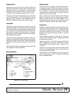
Remove cap nut (6a). Adjusting screw (6c) has a hex
socket - rotate screw clockwise to increase pressure
and counter-clockwise to decrease pressure.
Start tractor and engage PTO (for pump kits) set throt-
tle at PTO speed. Set system relief valve pressure at
2470 psi. When pressure is adjusted, shut tractor PTO
and tractor off. Replace cap nut (6a) on system valve.
Replacing Port Relief Valves
It is not necessary to remove valve from console to
replace port relief valve cartridges. Remove console
cover and replace them. Be sure you install valve car-
tridges set at the correct pressure. Valves are similar
and can be easily mixed up.
Segment Replacement
Relieve system pressure and remove valve from back-
hoe. Remove tie rods and separate the valve sections.
Replace defective sections as necessary. Make sure
you install two spacers between each section of each
tie rod. Note the location of O-rings (9 & 10). They must
be placed in the location between valve sections as
shown in Figure 15.
When assembling valve sections, use care when torqu-
ing nuts on tie rods. This must be done in steps - that is
to say, gradually increasing the tightening torque up to
Port Relief Valve Pressure Setting
4AA 2470 psi
4BB 2610 psi