


28 Dealer Service
MAN0450 (10/28/2005)
HYDRAULIC CYLINDER REPAIR
General Hydraulic Repair Information
The only repair parts available for these cylinders are
seal kits. If damage occurs to one of the cylinder com-
ponents, replace the cylinder.
NOTE: Before ordering seal kits, check stamping on
barrel. Part numbers ending with either "E" or "J"
require specific seal kits. See parts page 45 for correct
seal kit number.
A clean working area is essential for any hydraulic
repair.
All parts must be carefully cleaned before reassembly.
We recommend that when repairing hydraulic compo-
nents, you always replace existing seals with new
ones. Clean all components in solvent and blow dry
with low pressure air.
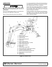
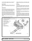
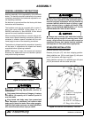
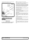
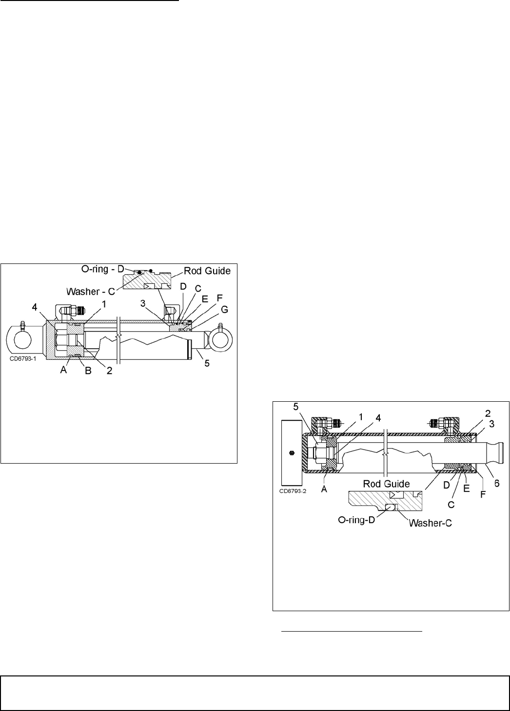
Spanner Nut with Round Retaining Ring
Style Rod Guide
Figure 17. Boom & Dipper Cylinder
Disassemble
On the 2-1/2" spanner nut type cylinders, Figure 17,
unscrew spanner nut from the end of the cylinder using
a spanner wrench, or carefully use a punch and ham-
mer.
Tap rod guide (3) into barrel about 1/2". Remove round
retaining ring (E). Pull rod (5) from end of barrel.
Clamp cross pin end of rod assembly in a vise with pro-
tective jaws. Remove nut (4) from rod assembly.
Remove piston (1) and rod guide (3) from rod.
Remove and discard all seals, wear rings and O-rings.
Clean all components in solvent and blow dry with low
pressure air.
Inspect inside of cylinder barrel and rod surface for any
scratches or scouring. Small scratches can be
removed with fine crocus cloth. If scratches cannot be
repaired, replace entire cylinder.
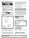
Assemble
Lubricate O-rings and seals with clean hydraulic fluid.
Install O-ring (D) and back-up washer (C) in exterior
groove of rod guide (3). Note the position of the backup
washer and O-ring. Install rod seal (F) into inner groove
of rod guide with open portion of V-groove toward pis-
ton.
Place rod wiper (G) in inner rod guide groove. Slide rod
guide assembly (3) onto rod (5). Place piston O-ring (2)
in groove. Install wear ring (A) and seal (B) on out side
of piston.
Slide piston onto rod. Apply Loctite
®1
primer 7649 and
removable thread lock 242 to end of rod. Install nut (4)
and torque to 150-180 lbs-ft.
Carefully insert piston and rod assembly into barrel.
Use care to prevent damage while installing.
Carefully push or tap rod guide (3) into barrel just past
groove inside barrel. Insert retaining ring (E) into
groove and pull rod (5) to seat rod guide (3) against
ring. Apply Loctite 242 to threads on guide. Screw
spanner nut onto guide using a spanner wrench, or
carefully use a punch and hammer.
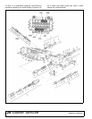
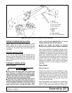
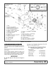
Snap Ring Style Rod Guide
Figure 18. Bucket & Stabilizer Cylinder
1. Piston
2. Piston O-ring
3. Rod guide
4. Nut
5. Rod
A. Wear ring
B. Piston seal
C. Backup washer
D. O-ring
E. Retaining ring
F. Rod guide seal
G. Wiper
1. Loctite is a registered trademark of the Henkel Loctite
Corporation.
1. Piston
2. Rod guide
3. Snap ring
4. Piston O-ring
5. Nut
6. Rod
A. Piston seal
C. Backup washer
D. O-ring
E. Rod guide seal
F. Wiper
(Rev. 8/5/2009)