


30 Assembly
MAN0450 (10/28/2005)
ASSEMBLY
GENERAL ASSEMBLY INSTRUCTIONS
Backhoe assembly is the responsibility of the WOODS
dealer. The backhoe should be delivered to the owner
completely assembled, lubricated and adjusted for nor-
mal operating conditions.
Set backhoe up as received from the factory with these
instructions and illustrations.
The backhoe must only be mounted with a tractor 3-
point hitch using WOODS 3-Point Mount kit or a
WOODS sub-frame kit. See WOODS 3-Point Mount
manual for mount installation instructions.
When mounting this backhoe on a tractor using a sub-
frame mount, special assembly instructions (which are
contained in another manual furnished with the sub-
frame) apply to some of the assembly procedures.
The backhoe is shipped partially assembled. Assembly
will be easier if components are aligned and loosely
assembled before tightening hardware.
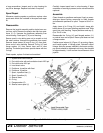
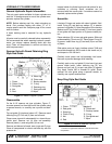
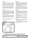
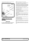
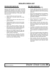
NOTE: References to right, left, forward and rearward
directions are determined from the backhoe operator
seat position facing rearward.
Figure 18. Backhoe Directions
Keep all persons away from operator control
area while performing adjustments, service, or
maintenance.
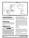
Only mount this backhoe on Category 1 tractors
with 800 lb. lift capacity at 24" behind 3-point lift
arm hitch balls.
Keep hands and body away from pressurized
lines. Use paper or cardboard, not hands or other
body parts to check for leaks. Wear safety goggles.
Hydraulic fluid under pressure can easily penetrate
skin and will cause serious injury or death.
Make sure that all operating and service person-
nel know that if hydraulic fluid penetrates skin, it
must be surgically removed as soon as possible by
a doctor familiar with this form of injury or gan-
grene, serious injury, or death will result. CON-
TACT A PHYSICIAN IMMEDIATELY IF FLUID
ENTERS SKIN OR EYES. DO NOT DELAY.
Always wear relatively tight and belted clothing
to avoid getting caught in moving parts. Wear
sturdy, rough-soled work shoes and protective
equipment for eyes, hair, hands, hearing, and head;
and respirator or filter mask where appropriate.
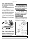
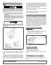
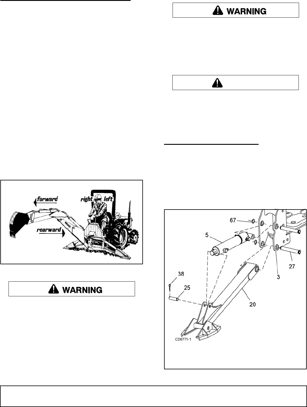
STABILIZER INSTALLATION
Remove stabilizer arms from pallet.
Remove pivot pins (27) from their shipping position.
Attach stabilizer arm (20) to main frame (3) with pivot
pin (27) and secure with snap ring (67).
Attach stabilizer cylinder (5) to stabilizer arm with pivot
pin (25) and secure with two cotter pins (38).
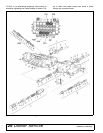
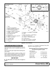
Figure 19. Stabilizer Arm Assembly - Left Side
CAUTION
3. Main frame
5. 2-1/2 x 11" Hyd cylinder
20. Stabilizer arm
25. Pin, .88 x 3.06"
27. Pivot pin, 1 x 6.67"
38. 3/16 X 1-1/2 Cotter pin
67. Ring, .042 x .925 ext.