


Dealer Service 27
MAN0450 (10/28/2005)
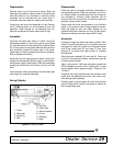
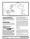
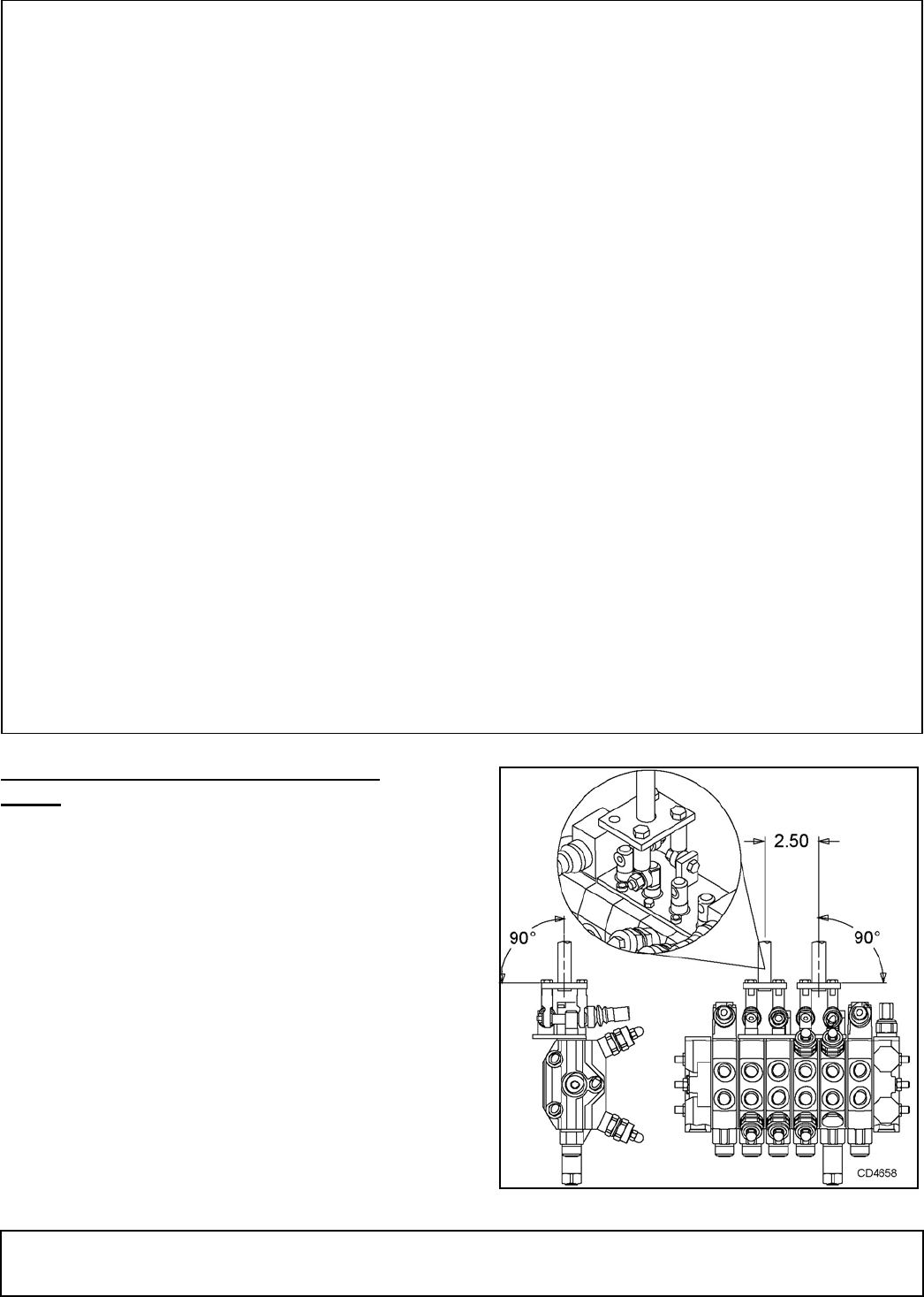
CONTROL VALVE LINKAGE ADJUST-
MENT
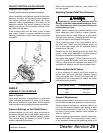
Reconnect control linkage to valve.
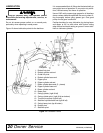
Control handles should be positioned with console as
shown.
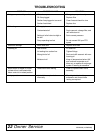
When completing a maintenance function on the valve,
perform a functional test by placing control handles in
their various positions and make certain the correct
operation occurs corresponding to the decals on the
operator's console. Pay specific attention to the float
position of the boom. Do not operate backhoe if func-
tions differ from the decal.
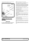
If the functions differ from the decal, check to make
sure control linkage is correctly installed and check
plumbing schematics to make sure hoses are correctly
connected. Figure 16. Control Lever Adjustment
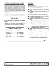
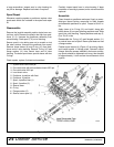
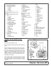
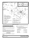
1. Complete hydraulic valve
2. Left stabilizer segment
3. Check valve assembly
a. Poppet
b. Spring
c. Seal
d. Car plug
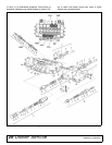
4AA. Shock/dampening valve, 2470
psi
4BB. Shock/dampening valve, 2610
psi
a. Cap nut
b. Washer
c. Adjusting screw
d. Retainer
e. Rear spring washer
f. Copper washer
g. Spring for relief valve
h. Front spring washer
i. Valve poppet
j. Back-up ring
k. Seal
l. Valve seat
m. Back-up ring
n. Washer
o. Ball, Dia. 5
6. 1350 - 3000 Psi Relief valve
assembly
a. Cap nut
b. Copper washer
c. Adjusting screw
d. Retainer
e. Copper washer
f. Rear spring washer
g. Spring
h. Front spring washer
i. Valve poppet
j. Valve seat
7. Spool position control 04
assembly
a. Plug for 04 positioner
b. Snap ring
c. Bushing for 04 positioner
d. Ball
e. Spring
f. Ball
g. Connecting bolt
h. Washer
i. Spacer
j. Spring for 04 positioner
k. Spring flange
l. Housing
n. O-ring
o. Flanged washer
p. Dowel bushing
q. Scraper
r. Lever bracket
s. Cap screw
t. Spool
8. Right stabilizer segment com-
plete
a. Plug
b. Housing
c. Connecting bolt
d. Spring cap
e. Spring
f. Spring cap
g. Spacer
h. O-ring
i. Valve segment
j. O-ring
k. Flanged washer
l. Dowel bushing
m. Scraper
n. Lever bracket
o. Cap screw
p. Spool
9. Seal
10. Seal
11. Spacer
12. Standard exhaust section
13. Front port inlet section
14. Boom segment
15. Swing segment
16. Dipper segment
17. Bucket segment
18. Nut
19. Tie rod