User manual W3532
- 17 -
hinge arm from the cutting mechanism and release the
draw of the arm. Draw out the cutting mechanism to
the left or right side. The assembly is performed in
the opposite procedure.
Adjustment of the height of the cutting
mechanism
When adjusting the cutting mechanism it is necessary to:
1. place the self-moving rotary cutter on a plain area
2. set the cutting mechanism to the lower position
3. loosen the arresting bolts of the draw bars of the front
hinge of the cutting mechanism
4. set the cutting mechanism into the required position
5. tighten the bolts of the draw bars of the front hinge
Replacement of driving belts
The power from the engine to the cutting mechanism is
transferred by means of the V-belt and the belt with double-
sided teeth. The driving belts must be replaced as soon as they
start to show symptoms of wear. Use only original belts!
Adjustment of the driving belt Engine – cutting
mechanism
The belt is permanently fastened with a spring-biased pulley
and, therefore, no additional adjustment or tensioning is
necessary.
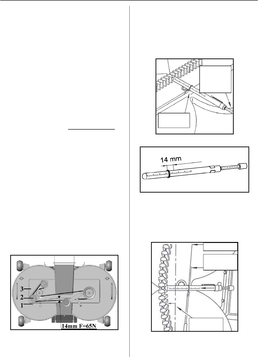
Adjustment of the driving belt for blade drives,
Fig.16
The tensioning of this belt is performed by the adjustment of
the nut (1) after the loosening of the bolt of the pulley (2) on
the lower side of the board (3).
A correctly tightened belt has a bend of 14 mm (in the middle
of the distance between the toothed belt pulley) with the
loading 65 N. After the tightening of the belt, tighten the
pulley bolt (2). After tightening, check the value of the
tightening of the belt.
Fig.16
Method of measurement and TENSION
TESTER No. 7401-0076 (possible to deliver on an
order basis)
Place the measuring preparation on the cover Fig.17 so that the
measuring device is in contact with the toothed belt – without
pressure. Shift the O ring up to the cover. Re-adjust the smaller
O-ring to the beginning of the power scale, Fig.17. Re-adjust
the greater O-ring to the required value by 14 mm, Fig. 18.
Fig.17
Fig.18
Catch the measuring instrument at the handle (read handle) and
press against the toothed belt for as long as the O-ring is in
contact with the wall of the cover Fig.19 and 20. Remove the
measuring instrument and ascertain to which value the O-ring
was shifted on the scale in N (v kg). In the case of the correct
tightening of the toothed belt on measuring route 14 mm, you
will achieve loading of 65 N (6.5 kg).
Fig.19
Measuring
ring must be
in contact with
the tested
body
Reference
point
Reference point
Move O-ring to the
reference point
Measurement
value


