A.8 WATLOW Series 988 User’s Manual
Appendix
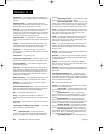
reset/integral adjustment 7.3
restore 6.14
retransmit 8.20 - 8.21, A.3
retransmit calibration offset 4.33
retransmit high limit 4.32
retransmit low limit 4.32
RTD A.3
RTD calibration curve 1 4.7
RTD calibration curve 2 4.14
RTD input 2.5
RTD wiring
input 1 2.8
input 2 2.9
RTU Modbus 8.4
S
safety practices 2.4, 2.6, 2.7
semiconductor oven 8.3
sensor installation 2.5
sensor type
input 1 4.3
input 2 4.9 - 4.10
serial number 6.8
set point, in tuning 7.2 - 7.3
set point, ramp to 8.16 - 8.17
set point 1 3.2
set point 2 5.1, 5.3
set point 2 control 4.22
setting DIP switches 1.1 - 1.4
input 1.2
lockout 1.4
output 1.3
Setup Menus 4.1 - 4.48
shipping claims A.5
silencing 2 4.24
silencing 3 4.27
silencing 4 4.30
silencing alarms 7.7
slidewire feedback 8.22 - 8.23, A.3
slidewire feedback wiring 2.10
slidewire hysteresis 4.16
software filter 1 4.7
software filter 2 4.15
software revision 6.8
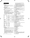
specifications A.4
square root extraction (linearization,
square root) 8.14 - 8.15, A.2
storing data 8.4 - 8.5
switched dc, open collector wiring
output 1 2.12
output 2 2.13
output 3 2.14
output 4 2.15
switching sensitivity A.3
System Menu 5.1 - 5.8
lockout 6.4
T
technical assistance iii, 6.10
temperature limit control protection 2.6
terminal designation stickers 2.4
test chambers
wih communications 8.5
test displays 6.11
test output 6.11
thermal system A.3
thermocouple 2.5, A.3
thermocouple break protection A.3
thermocouple wiring
input 1 2.8
input 2 2.9
three-mode control A.3
time constant, filter
input 1 4.7
input 2 4.15
time proportioning control A.3
tuning
automatic 7.1 - 7.2
manual 7.2 - 7.4
settings 7.2 - 7.3
Tuning of Industrial Control Systems 7.1
U
Up-arrow Key 3.1
upper display 3.1
using manual ii - iii
V, W
warnings iii
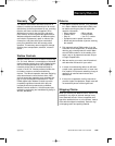
warranty A.5
waste-water treatment 8.15
wiring 2.1, 2.4 - 2.15
event input 1 2.11
event input 2 2.10
input 1 2.8
input 2 2.9 - 2.10
output 1 2.12
output 2 2.13
output 3 2.14
output 4 2.15
wiring example 2.6
wiring safety 2.4, 2.6, 2.7
X, Y, Z
zero switching A.3
zone heating 8.19
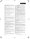
Prompt Index
[----] (error) 7.8
A
[A2HI] (alarm 2 high) 5.5, 8.17
[A2LO] (alarm 2 low) 5.4, 8.17
[A2Sd] (alarm 2 side) 4.23
[A3HI] (alarm 3 high) 5.6
[A3LO] (alarm 3 low) 5.5
[A3Sd] (alarm 3 side) 4.26
[A4HI] (alarm 4 high) 5.7
[A4LO] (alarm 4 low) 5.6
[A4Sd] (alarm 4 side) 4.29
[ACAL] (retransmit calibration offset) 4.33
[Actn] (control output action) 8.8
[Addr] (device address) 4.46
[`AL2] (alarm 2) 4.23
]AL2n] (alarm 2 reverse) 7.6
[`AL3] (alarm 3) 4.25
[AL3n] (alarm 3 reverse) 7.6
{~AL4} (alarm 4) 4.28
[AL4n[ (alarm 4 reverse) 7.6
[ALgO] (algorithm) 4.38
[`ALr] (alarm reset) 8.8
[AMb] (ambient temperature) 6.8
[Anun] (annunciator) 4.41
[Aout] (analog output) 4.31
[`ArH] (retransmit high limit) 4.32
[`ArL] (retransmit low limit) 4.32
[AtSP] (auto-tune set point) 4.42, 7.1
[`AUt] (auto-tune) 5.7, 7.2
B
[bAUd] (baud rate) 4.45
[both] (alarm 3 trigger) 4.26
[bPLS] (bumpless transfer) 4.35
[brSt] (burst fire) 8.2
C
[`C_F] (Celsius_Fahrenheit) 4.35
[`CAL] (calibration lockout) 6.6
[`CAL] (Calibration Menu) 6.13
[CAL1] (calibration offset 1) 4.6
[CAL2] (calibration offset 2) 4.14
[CntL] (control type) 4.36
[COM] (Communications lockout) 6.6
[COM] (Communications Menu) 4.44, 8.4
[CSAC] (cascade action) 4.37
[CSCd] (cascade control) 4.36
[Ct1A] (cycle time, output 1, PID A) 5.13, 8.2
[Ct1b] (cycle time, output 1, PID B) 5.13, 8.2
[Ct2A] (cycle time, output 2, PID A) 5.16, 8.2
[Ct2b] (cycle time, output 2, PID B) 5.16, 8.2
[Curr] (current) 8.10, 8.11
D
[dAtA] (data bits & parity) 4.45, 8.4
[DAtE] (factory ship date) 6.8
[``db] (dead band) 5.16
[db`A] (dead band PID A) 5.16, 8.6
[db`b] (dead band PID B) 5.16, 8.6
[`dE1] (deviation alarm input 1) 7.6
[`dE2] (deviation alarm input 2) 7.6
[dE1A] (derivative, output 1, PID A) 5.12
[dE1b] (derivative, output 1, PID B) 5.12
[dE2A] (derivative, output 2, PID A) 5.15
[dE2b] (derivative, output 2, PID B) 5.15
[dEC1] (decimal 1) 4.4
Index r-z
C Appendix.wc 5/14/1999 8:33 AM Page A.8


