


6
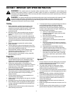
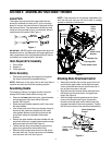
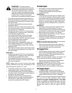
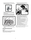
• If not already attached, slip the cables that run from
the handle panel to the chute assembly into the
cable guide located on top of the engine. See
Figure 4.
• If not already attached, unwrap the headlight wire
which is attached to the headlight, beneath the
handle panel. Wind the headlight wire around the
lower right handle until excess slack is removed.
See Figure 4.
Figure 4
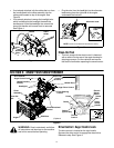
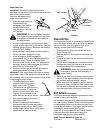
• Plug the wire from the headlight into the alternator
lead coming from the right side of the engine
underneath the fuel tank.
Figure 5
Clean-Out Tool
• This tool, along with the electric cord, is fastened
with a cable tie to the rear of the auger housing for
shipping purposes. Cut the cable tie and remove
the electric cord before operating the snow thrower.
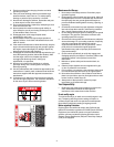
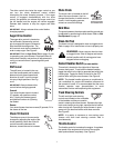
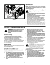
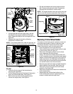
SECTION 3: KNOW YOUR SNOWTHROWER
Figure 6
WARNING: Read, understand, and follow
all instructions and warnings on the machine
and in this manual before operating.
Drive Control / Auger Control Lock
The drive control is located on the right handle.
Squeeze the drive control to engage the wheel drive.
Release to stop. See Figure 6.
Cable
Discharge
Chute
Guide
Cables
Alternator Lead
Lamp Wire
Alternator
Lead
NOTE:
Tracks are omitted from illustration for clarity.
Drive Control /
Auger Control Lock
Shift Lever
Auger Drive Control
Skid Shoe
Auger
Headlight†
Chute
Assembly
Track Steering
Control
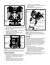
Switch
Box
Electric
Starter
Button
Recoil
Starter
Handle
Primer
Choke
Safety
Ignition Key
Throttle
Control
Chute Tilt
Control
Heated Handles
Switch†
Chute Directional
Control
Clean-Out
Tool
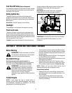
Closed
Open
Fuel Shut-Off Valve
*If Equipped
Heated Grip†
† Optional