


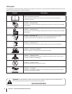
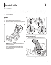
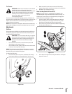
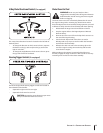

Tire Pressure
Under any circumstance do not exceed
pressure should be maintained at all times. Excessive
pressure when seating beads may cause tire/rim
assembly to burst with force sufficient to cause
serious injury. Refer to side wall of tire for
recommended pressure.
The tires are over-inflated for shipping purposes. Check the tire
pressure before operating the snow thrower. Refer to the tire side
inflate) the tires as necessary.
NOTE: If the tire pressure is not equal in both tires, the machine may
not travel in a straight path and the shave plate may wear unevenly.
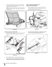
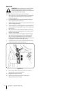
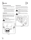
Adjustments
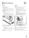
Skid Shoes
The snow thrower skid shoes are adjusted upward at the factory
for shipping purposes. Adjust them downward, if desired, prior
to operating the snow thrower.
It is not recommended that you operate
this snow thrower on gravel as it can easily pick up
and throw loose gravel, causing personal injury or
damage to the snow thrower and surrounding
property.
For close snow removal on a smooth surface, raise skid
shoes higher on the auger housing.
Use a middle or lower position when the area to be cleared
is uneven, such as a gravel driveway.
NOTE: If you choose to operate the snow thrower on a gravel
surface, keep the skid shoes in position for maximum clearance
between the ground and the shave plate.
To adjust the skid shoes:
Loosen the four hex nuts (two on each side) and carriage
Make certain the entire bottom surface of skid shoe is 2.
against the ground to avoid uneven wear on the skid shoes.
Retighten nuts and bolts securely.3.
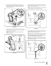
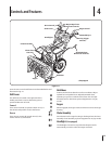
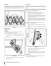
Chute Assembly (Models 2410 and 2620)
NOTE:
The distance snow is thrown can be adjusted by changing the
angle of the chute assembly. To do so:
Remove the key from the engine and loosen the plastic
knob found on the left side of the chute assembly.
2.
Insert Key into engine and start engine. Refer to the Engine 3.
11se c t i O n 3 — as s e M b l y & se t-up