


Rev. B
Workman MD/MDX Drive TrainPage 5 -- 7
Adjustments
Adjust Ground Speed (Workman MD with Serial Number Below 313000400)
Workman MD models with serial number below
313000400 are equipped with a transaxle governor. Ad-
just ground speed using the following procedure for
these vehicles.
Vehicles operating at ground speeds greater than
the recommended speed will require further
distances to fully stop. Do not adjust ground
speed greater than specified.
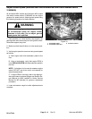
WARNING
1. Park machine on a level surface, stop engine and re-
move key from the ignition switch. Raise and support
cargo box.
WARNING
Before jacking up the mach ine, review and follow
Jacking Instructions in Chapter 1 -- Safety.
2. Jack up rear of vehicle so both rear wheels are at
least 1 inch (25mm) off the ground. Support the rear axle
tubes on appropriate jack stands.
3. Chock front and rear of both front tires to prevent the
vehicle from moving.
4. Make sure that the shift lever is in the neutral posi-
tion.
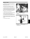
5. Verify ground speed as follows:
A. Start engine and hold accelerator pedal to the
floor.
B. Verify driven clutch RPM with a tachometer. With
the accelerator pedal to the floor, the driven clutch
speed should be from 3550to3650RPM.
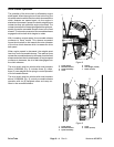
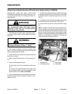
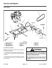
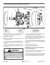
6. If ground speed adjustment is necessary, drill out an-
odized r ivet and retain anti--tamper bracket for rein-
stallation (Fig. 9).
7. Adjust throttle cable (accelerator pedal to transaxle)
at the cable bracket until the correct driven clutch RPM
is obtained with the accelerator pedal fully to the floor
(Fig. 9).
8. Install anti--tamper bracket to the cable bracket using
a new anodized rivet (Toro P/N 99--7122) (Fig. 9).
9. Lower machine to ground. Lower and secure cargo
box.
NOTE: If unable to identify the driven clutch RPM, an al-
ternate method to verify ground speed would be to de-
termine the distance that the vehicle will travel on level
ground in three (3) seconds with the accelerator pedal
to the floor. The Workman MD should travel 62 feet (18.8
meters) in three seconds. If necessary, adjust ground
speed using steps 6 through 8 above.
1. Anodized rivet
2. Anti--tamper bracket
3. Throttle cable
4. Cable bracket
Figure 9
3
1
2
4
Drive Train